96 MS 650, MS 660
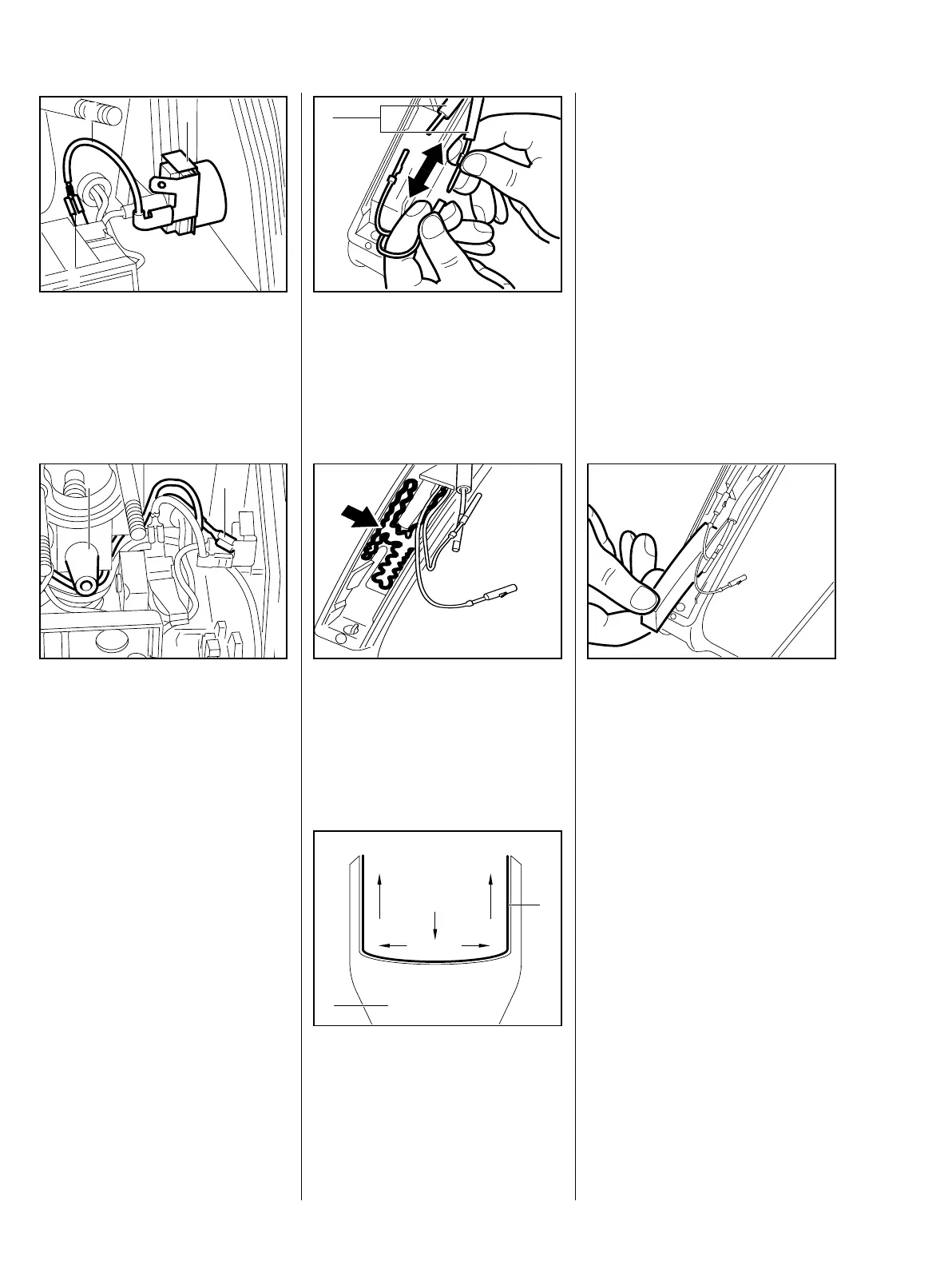
: Fit the short circuit wire (1)
between the connector tags (2)
and contact spring (3).
178RA239
VA
2
1
3
: Push the wires (1) onto the
connector tags.
– Position the wires under the
impulse hose (2).
– Install the carburetor – b 12.2.1
178RA240
VA
2 1
– Remove the upper handle
molding – b 10.1
: Slide the two insulating tubes (1)
off the pin and socket connectors
and separate the connectors.
1
VA
176RA225
: Take pressure pad and heating
element out of the handle recess.
Before fitting the new heating
element, clean the surface inside
the handle so that it is free from
grease, dirt and moisture.
VA
176RA337
– Removing the backing from the
new heating element.
: Place heating element (1) in
handle housing (2) and press
firmly and uniformly into position,
from the center outwards.
VA
176RA336
1
2
Avoid creases. If the heating
element is not fitted perfectly flat,
heat transfer will be interrupted and
the element may fail as a result of
overheating. The ambient
temperature during installation
should not be less than + 15°C
(59°F).
Reassemble in the reverse
sequence.
: Fit a new expanded rubber
pressure pad on top of the
heating element. The heating
element must be completely
covered.
Reassemble all other parts in the
reverse sequence.
VA
176RA227
Check operation of heating
element
Run the saw at maximum revs for
no more than 30 seconds with the
heating switched on.
14.3 Heating Element in
Rear Handle