30 SR 430, SR 450
5. Ignition System
Exercise extreme caution when
troubleshooting and carrying out
maintenance or repair work on the
ignition system. The high voltages
which occur can cause serious or
fatal accidents.
Troubleshooting on the ignition
system should always begin at the
spark plug, b 3.3
– Remove the shroud, b 4.4
The electronic (breakerless) ignition
system basically consists of an
ignition module (2) and flywheel (1).
5.1 Ignition Timing
Ignition timing is fixed and cannot
be adjusted during repair work.
Since there is no mechanical wear
in these systems, ignition timing
cannot get out of adjustment during
operation.
0002RA064 TG
1
2
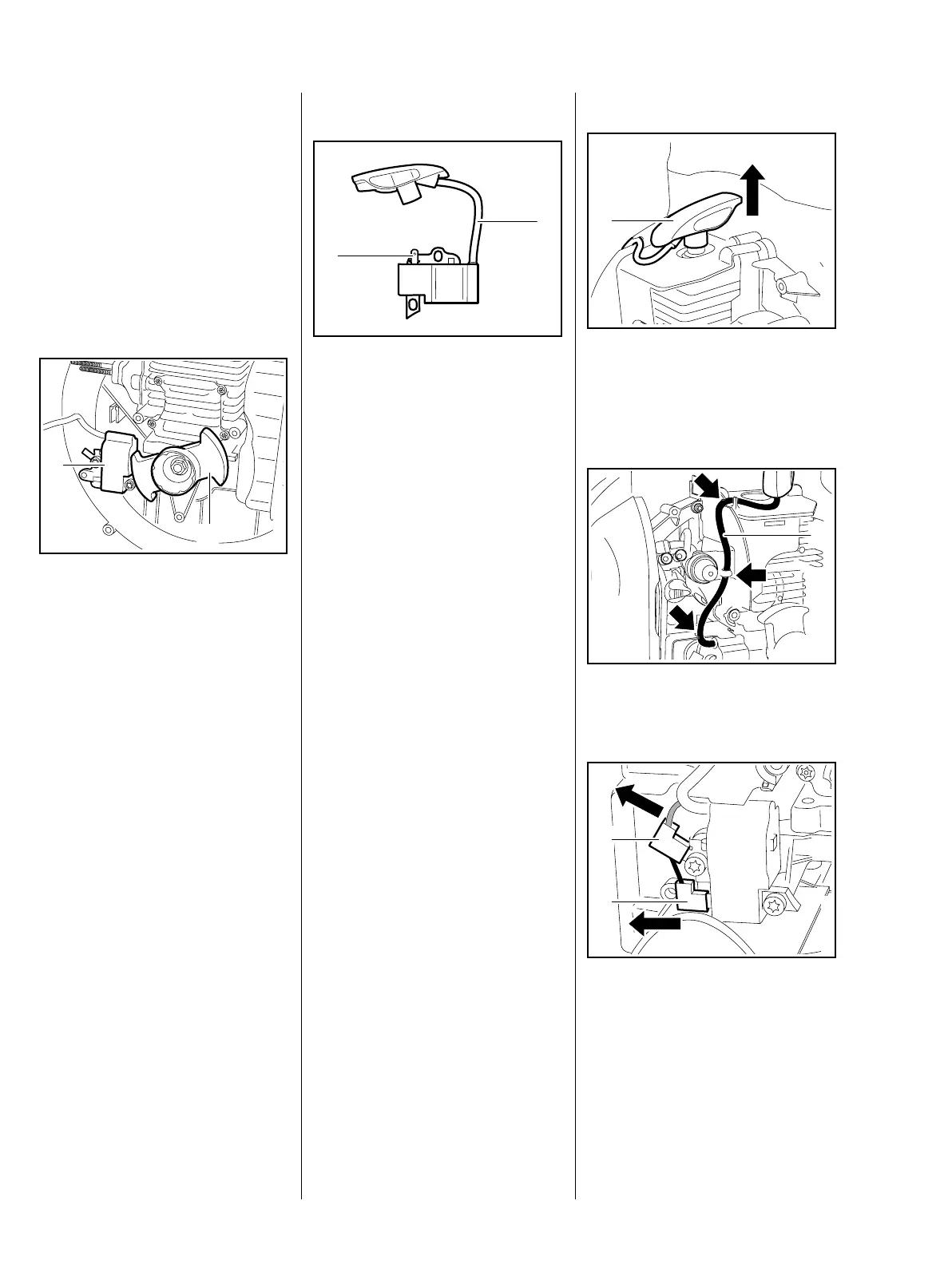
5.2 Ignition Module
The ignition module accommodates
all the components required to
control ignition timing. There are
two electrical connections on the
coil body:
– High voltage output (1) with
ignition lead
– Connector tag (2) for the short
circuit wire
Testing in the workshop is limited to
a spark test. A new ignition module
must be installed if no ignition spark
is obtained (after checking that
wiring and stop switch are in good
condition), b 5.3
0002RA065 TG
1
2
Removing
– Remove the shroud, b 4.4
: Pull off the spark plug boot (1)
vertically.
: Pull the ignition lead (1) out of the
guides (arrows).
: Disconnect the short circuit
wire (1) and ground wire (2).
0002RA066 TG
1
0002RA200 TG
1
0002RA025 TG
1
2