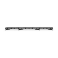
K-FORCE® FULL BAR SERIES
SpeedTech Lights, Inc © 2018
*Trac Advisor Buttons
The Trac Advisor LEDs will ash in sequence with the warning pattern when not activated
• <- Left Trac Advisor Signal
• <--> Center Out Trac Advisor Signal
• -> Right Trac Advisor Signal
*Flash Pattern Button
• Changes the ash pattern with each press. Non-Volatile memory recalls the last ash pattern.
*Cruise (Four 45° (corner) warning modules)
• 1st press: Steady burn
• 2nd press: Pulsing Flash
• 3rd press: Flash in the same sequence/ash pattern as the bar
*Aux [Red (+) Positive] and Blue [(-) Negative wires]
• Rated for 10 AMPs
• 1st press: Power ON unit attached to aux cables
• 2nd press: Power OFF unit attached to aux cables
*These functions can be operated independently of the Light Bar’s warning lights being activated
Wiring: Connecting Wires to the Battery
WARNING! If you are supplying your own wiring that connects to the positive or negative terminal of the battery, fuse sizes must be sized according
to STL’s provided fuse to be considered fused properly to the battery in order to carry the load.
• Route the power cables by opening the wiring shield and running the cables through it towards your vehicle’s rewall.
• Follow the factory wiring harness through the rewall.
• If it is necessary to drill a hole in the rewall for the power cables, be sure no components will be damaged from drilling. As with all holes
that are drilled, le the edges down smooth and insert a grommet to protect the cables.
• Route the cable along the factory wiring harness towards the battery.
• Wire your power cables (Red with In Line Fuse (STL Supplied) and Black cable) to your battery to power up your Light Bar.
• You will want to ensure your grounding cable is taken directly to the negative terminal of your battery to avoid any electrical feedback which
may disrupt your Light Bar system.
• DO NOT allow the positive (Red wire) and negative (Black wire) to touch one another. This may cause injury to you and damage your equip-
ment by causing a short in the unit that is not covered under the STL warranty.
Wiring: Connecting Wires to Control Box
• This unit will feature a power harness with sixteen (16) colored leads with a connector that plugs into the Supreme Control® Box. When not
utilizing the Supreme Control® Box reference the Wiring Diagram above.
• Now that you have pulled the cable into the vehicle attach the connector back to your Light Bar’s wire harness in the CORRECT positions
using a pin pusher and plug it into your Supreme Control® Box. If you do not know the correct position of each wire in the connector call
customer service at 800-757-2581 before proceeding.
• If you did not purchase the Supreme Control® Box and are using your own switch box or the STL IntelliSiren, wire the cables accordingly into
your control panel by referencing the wiring diagram and instruction manual of your control panel.
Wiring: Connecting Extension Cables
• This unit will feature a power harness with sixteen (16) colored leads with a connector that plugs into the Supreme Control® Box.
• If you have an extension cable with connectors, connect the corresponding ends to one another. Use the connector at the end of the cable
to plug into your control box.
• If you have an extension cable with one connector, you will need to cut the connector o of the main cable harness coming out of the Light
Bar. Save it as a spare part. You will solder, and heat shrink each wire within the cable harness to each wire in the extension cable harness. DO
NOT cross connect wires. Use the connector at the end of the extension cable to plug into your control box.
• If you have an extension cable with no connectors, you will need to cut in the middle of the main cable harness coming out of the Light
Bar. You will solder, and heat shrink each wire within the cable harness to each wire in the extension cable harness. DO NOT cross connect
wires. Use the connector at the end of the main cable harness to plug into your control box. DO NOT leave connectors, cables, solder points
exposed to heat or moisture or debris.
 Loading...