Description UM2516
10/29 UM2516 Rev 4
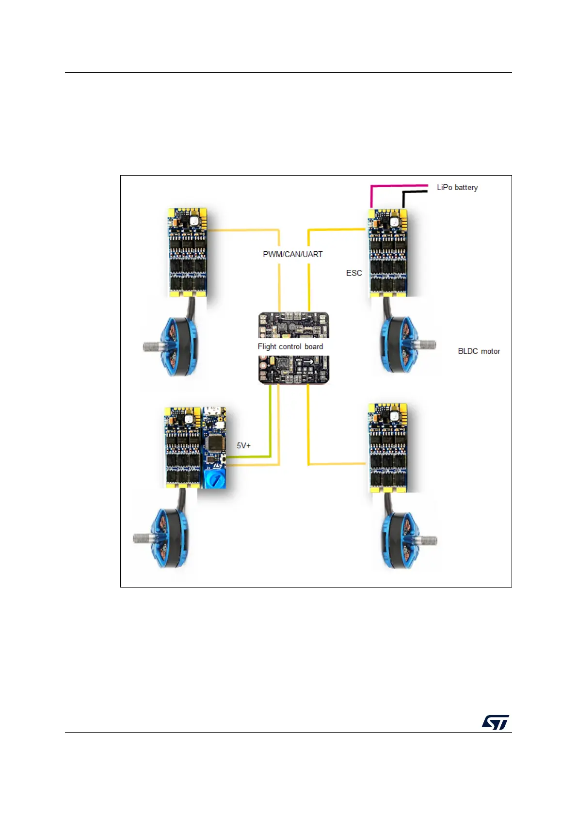
The typical system architecture is shown in Figure 4.
Each ESC board is connected with a single brushless motor, in this case, a quadcopter
system is taken as an example. An external LiPo battery provides the right power to the four
connected boards and through a wired bus, each ESC board receives or sends commands
from or to an external unit, for instance, a flight control unit.
Figure 4. System structure overview
The B-G431B-ESC1 provides the maximum flexibility in term of communication protocol
(UART, PWM, and CAN are available on-board), and it also contains a DC-DC converter on
the daughterboard, with 5
V output connector (BEC) to supply an external board, for
instance, a flight control unit or sensors.