Connection and first execution of the electronic speed controller (ESC) program UM2516
20/29 UM2516 Rev 4
Figure 13. ST MC Workbench screen
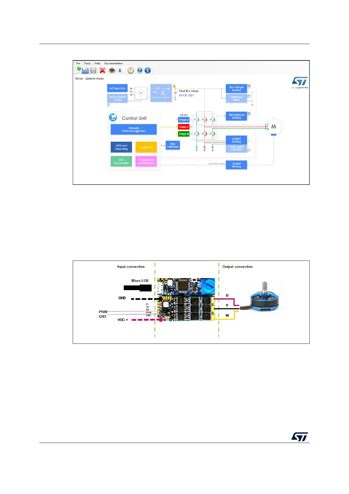
4. Solder the three motor wires U, V, W at the motor (J7) solder pad with no particular
color sequence (see
Figure 14)
5. Solder the PWM input and GND at J3 connector (pin 4 and pin 5). The PWM input
signal is either 3.3
V or 5 V (the PWM is connected to a 5 V tolerant MCU input pin).
6. Connect the main board with a LiPo battery (or DC power supply: min 3S - max 6S)
with the right polarity and turn ON. The input connector is composed of two large pads
for soldering. The Transil device prevents damage in case of reverse polarity at the
input side for a low time.
Figure 14. B-G431B-ESC1 I/O connection