UM2516 Rev 4 21/29
UM2516 Connection and first execution of the electronic speed controller (ESC) program
28
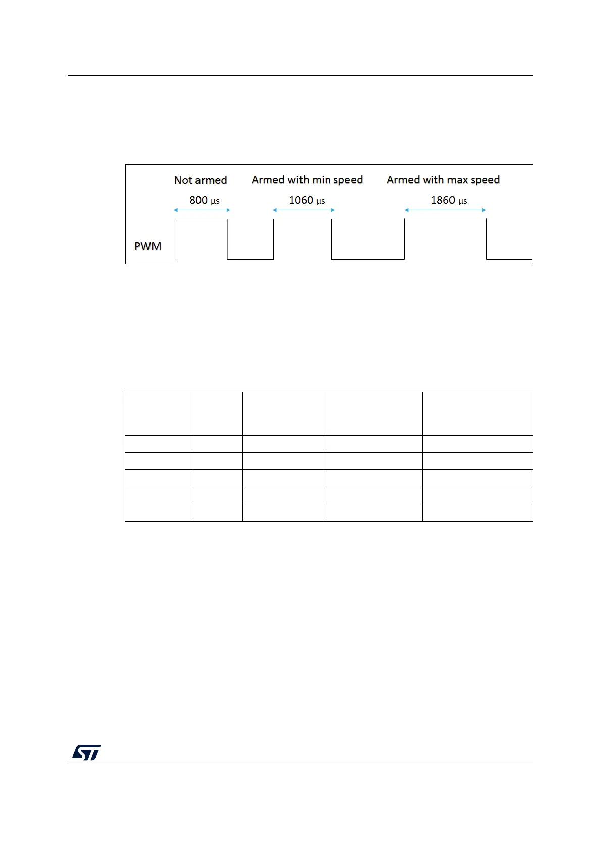
7. Generate on J3 connector a PWM signal at 490 Hz and duty cycle value between
1060
µs and 1860 µs, the motor starts to rotate respectively from the minimum to the
maximum speed. The ESC is not armed (no driving signals generated) if the duty cycle
is lower than 1060
µs.
Figure 15. PWM input signal for motor speed regulation
Note: In case the motor is already started, a blank time of 1500 ms on the PWM signal determines
the switch off of the system (ESC turned OFF).
6.2 Second case: daughterboard removed
In case the daughterboard is removed, Table 6 shows the relation between the SWD pinout
on the main board and SWD on ST-LINK/V2 (not isolated version) external programmer.
Set the SWD interface inside the IDE tool, for instance, a picture of IAR Workbench is
shown in
Figure 16.
If the daughterboard is removed the following pad connections are available on it:
• On the top side -> SWDIO, SWCLK
• On the bottom side -> NRST, +10V,+5V, 5V_ESC, GND
Table 6. SWD connector for MCU programming (daughterboard removed)
Pin no. in
STLINK
ST-
LINK/V2
connector
ST-LINK/V2
function
Target connection
(SWD)
Pin no. in DK B-G431B-
ESC1 (J4 pad)
1 VAPP Target VCC MCU VDD 3
2 VAPP Target VCC MCU VDD 3
6 GND - GND 4
7 - SW IO SWDIO 1
9-SW CLKSWCLK 2