EasyManuals Logo

STMicroelectronics B-G431B-ESC1 User Manual

STMicroelectronics B-G431B-ESC1
29 pages
To Next Page IconTo Next Page
To Previous Page IconTo Previous Page
Page #16 background imageLoading...
Page #16 background image
Hardware layout and configuration UM2516
16/29 UM2516 Rev 4
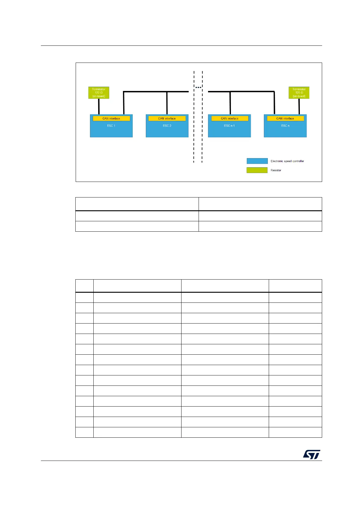
Figure 11. ESC connections with CAN communication
5.6 STM32G431CB pinout for motor control
Table 3. Truth table
CAN_TERM pin
120 resistor
HON
LOFF
(1)
1. High impedance
Table 4. Main board STM32G431CB pinout for motor control
Pin Default Signal Solder Bridge
1VBAT 3V3 -
2 PC13/TAMP/RTC TIM1_CH1N -
3 PC14 CAN_TERM R26
4PC15 N.C. -
5 PF0/OSC-IN OSC 8Mhz -
6 PF1/OSC-OUT OSC 8Mhz R27
7 PG10/NRST RESET -
8 PA0 VBUS -
9 PA1 Curr_fdbk1_OPAmp+ -
10 PA2 OP1_OUT -
11 PA3 Curr_fdbk1_OPAmp- -
12 PA4 BEMF1 -
13 PA5 Curr_fdbk2_OPAmp- -
14 PA6 OP2_OUT -

Table of Contents

Questions and Answers:

Question and Answer IconNeed help?

Do you have a question about the STMicroelectronics B-G431B-ESC1 and is the answer not in the manual?

STMicroelectronics B-G431B-ESC1 Specifications

General IconGeneral
BrandSTMicroelectronics
ModelB-G431B-ESC1
CategoryController
LanguageEnglish

Related product manuals