UM2516 Rev 4 17/29
UM2516 Hardware layout and configuration
28
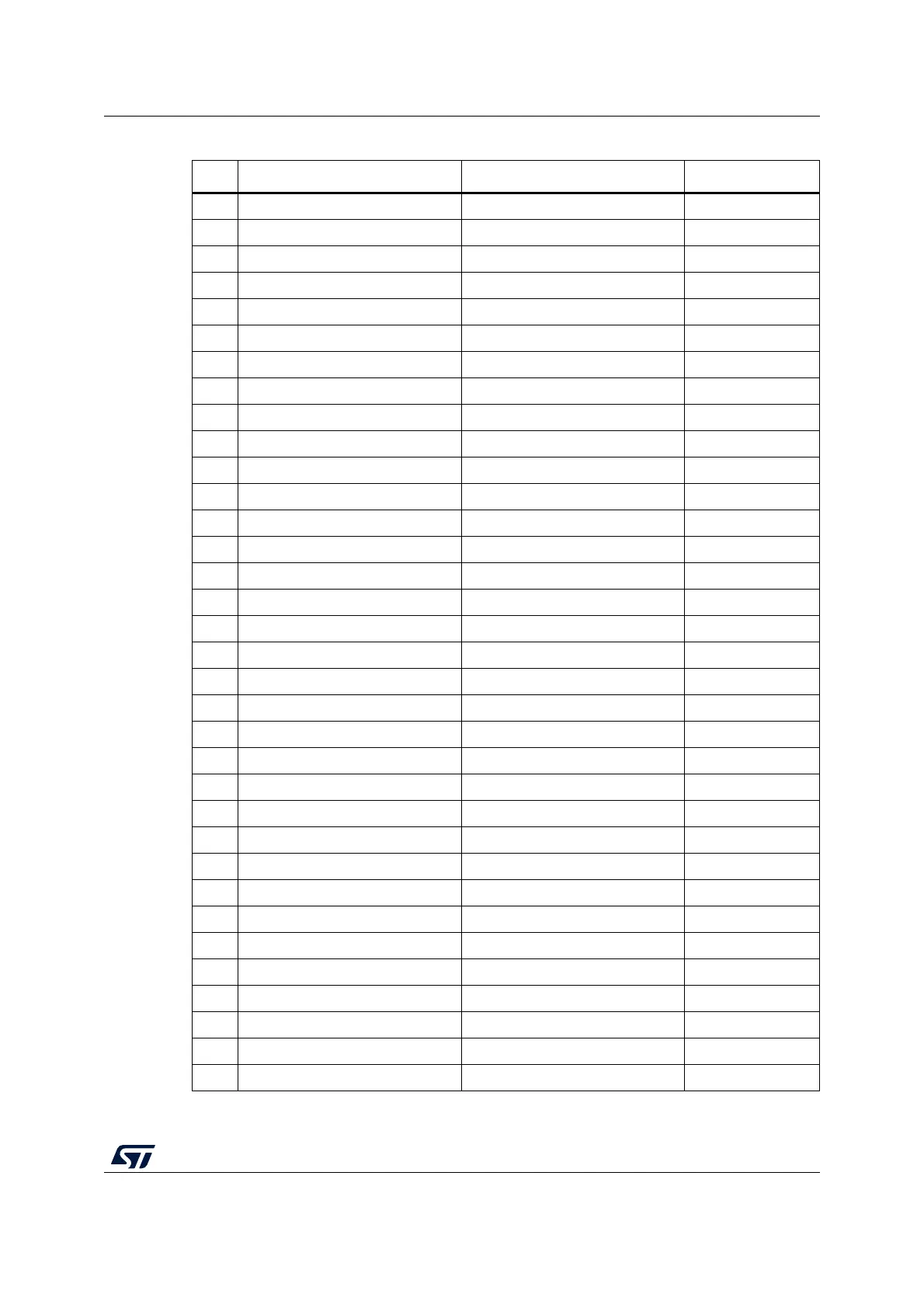
15 PA7 Curr_fdbk2_OPAmp+ -
16 PC4 BEMF2 -
17 PB0 Curr_fdbk3_OPAmp+ -
18 PB1 TP3 -
19 PB2 Curr_fdbk3_OPAmp- -
20 VREF+ 3v3 -
21 VDDA 3v3 -
22 PB10 N.C. -
23 VDD4 3V3 -
24 PB11 BEMF3 -
25 PB12 POTENTIOMETER -
26 PB13 N.C. -
27 PB14 Temperature feedback -
28 PB15 TIM1_CH3N -
29 PC6 STATUS -
30 PA8 TIM1_CH1 -
31 PA9 TIM1_CH2 -
32 PA10 TIM1_CH3 -
33 PA11 CAN_RX -
34 PA12 TIM1_CH2N -
35 VDD6 3V3 -
36 PA13 SWDIO -
37 PA14 SWCLK -
38 PA15 PWM -
39 PC10 BUTTON -
40 PC11 CAN_SHDN,TP2 -
41 PB3 USART2_TX -
42 PB4 USART2_RX -
43 PB5 GPIO_BEMF -
44 PB6 A+/H1 -
45 PB7 B+/H2 -
46 PB8 Z+/H3 -
47 PB9 CAN_TX -
48 VDD8 3V3 -
Table 4. Main board STM32G431CB pinout for motor control (continued)
Pin Default Signal Solder Bridge