UM2516 Rev 4 15/29
UM2516 Hardware layout and configuration
28
The J4 solder pads provide the SWD connection between the STM32G431CB and the
external ST-LINK programmer if the daughterboard is removed. In this case, other pins are
available, such as 3V3 and GND.
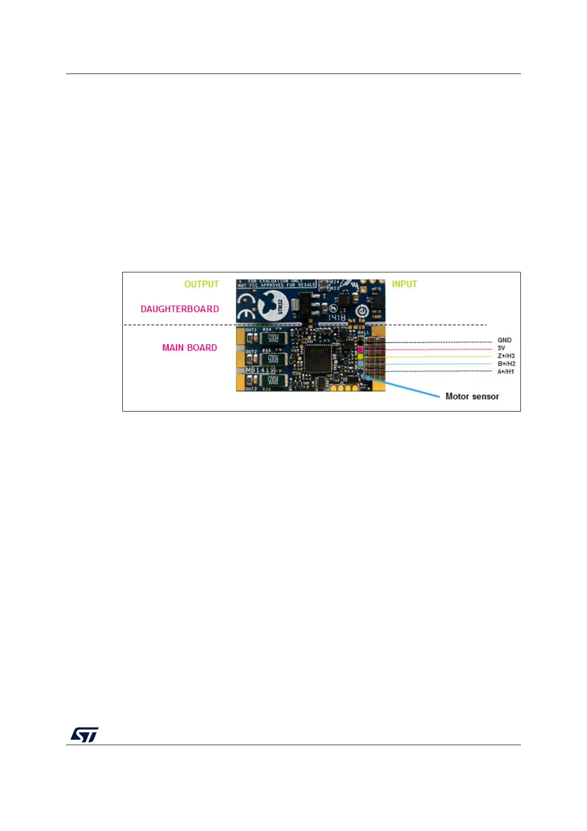
The J8 solder pads allow the connection of the motor sensor, Hall, or encoder. Refer to
Section 5.4 for further information.
5.4 Motor sensor connection (Hall or encoder)
The Discovery kit embeds the hardware circuit for Hall or encoder sensor. A supply voltage
line is provided with 5
V and GND lines in J8 solder pads. This voltage is available also if the
daughterboard is removed. The ST MC workbench must be configured to use these sensors
during the FOC control.
Figure 10. Motor sensor connection
5.5 CAN connection and configuration
The main board includes the transceiver and the connection pads to use the CAN peripheral
available in the STM32G431CB MCU. The hardware circuit is based on UAVCAN standard
(https://uavcan.org/) so a little fuse is included to protect by overcurrent so that an
accidental short circuit on the device does not bring down the power on the entire bus. One
CAN output (J1) is provided on-board and T-connectors are needed to create the bus line
with several boards.
This circuit accepts also the supply voltage from the external unit, for example, a flight
control unit with a power CAN (5.0
V to 5.5 V on the bus power line). In this case, J1 solder
pads contain the 5V line (input) and if a voltage is applied to it, the main board generates the
3.3
V for G4MCU and the transceiver. This feature allows keeping the communication also
when the battery is discharged or removed.
Figure 11 shows that two terminator resistors
are needed to open and close the CAN bus line. B-G431B-ESC1 includes this terminator
resistor (120
Ω) and it is manageable by firmware (CAN_TERM pin) with a low voltage
single-pole-double-throw analog onboard switch (see the CAN page on the electrical
schematic).
Table 3 shows the logic to add or remove this resistor.