UM1932 Rev 3 21/30
UM1932 Hardware layout and configuration
29
4.14 DSI LCD
The LCD module is a 4-inch 800x480 TFT color LCD with capacitive touch panel. The LCD
is connected to the MIPI DSI interface of the microcontroller STM32F469NIH6 via the
connector CN10. The DSI (Display Serial Interface) is a specification of the MIPI Alliance
standard and defines the physical interface and the protocol used by the STM32F469NIH6
microcontroller to communicate with such LCD module.
The following ports of the microcontroller STM32F469NIH6 are dedicated to the DSI
interface: DSI_D0_N, DSI_D0_P, DSI_CK_N, DSI_CK_P, DSI_D1_N, DSI_D1_P.
In addition to the DSI dedicated ports, the port PH7 of the microcontroller is used to reset
both the DSI LCD module and the capacitive touchscreen controller.
The port PJ2, connected to the LCD signal TE (Tearing Effect) is an input of the
microcontroller to synchronize the write access from the microcontroller with the LCD scan
refresh, to avoid visible artefacts on the display.
LEDK and LEDA signals of the LCD module are the cathode and anode of the backlight
LEDs.
This backlight requires a power supply voltage of typically 25 V generated from the +5 V by
a switching mode boost converter STLD40DPUR.
By controlling the EN pin of the STLD40DPUR by a low frequency PWM signal, it is possible
to switch on/off or to dim the backlight intensity of the LCD module. The control of EN can be
done by software or by hardware:
• By default, the EN pin of the STLD40DPUR is controlled by the microcontroller
software through DSI commands and CABC signal generated by the LCD module. For
such default configuration the resistor R117 is soldered, R119 is not soldered.
• The STM32F469I-DISCO Discovery board offers the option to control the EN pin by
HW through port PA3. In such case, R117 must be removed and R119 soldered.
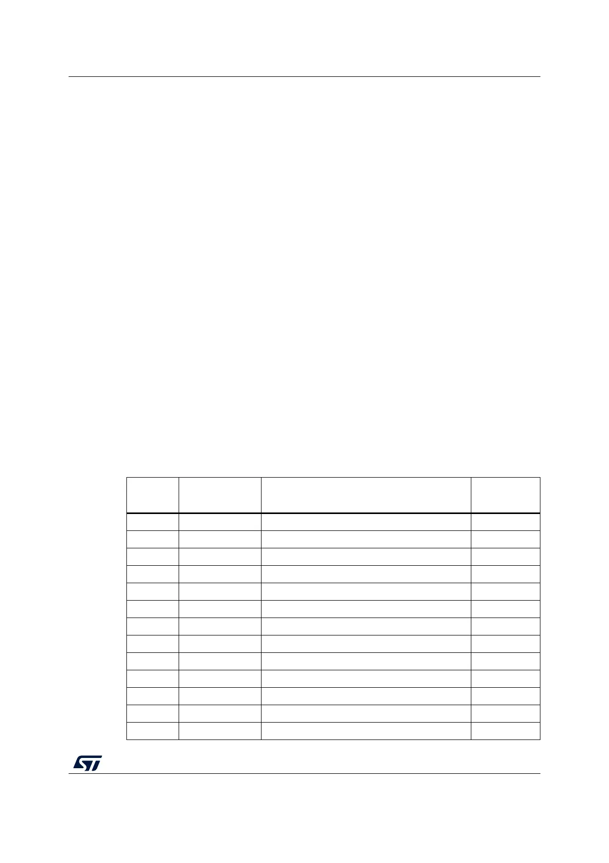
Table 7. DSI LCD module connector (CN10)
CN10
pin
Signal
name
Description
MCU pins
involved
1 ID Not connect -
2 GND Ground -
3 CABC Content Adaptive Brightness Control -
4 GND Ground -
5 RESX Reset, active low PH7
6 IOVCC Digital supply voltage +3V3
7 GND Ground -
8 HSSI_D0_N MIPI-DSI data lane 0 negative-end I/O DSI_D0_N
9 NC Not connect -
10 HSSI_D0_P MIPI-DSI data lane 0 positive-end I/O DSI_D0_P
11 GND Ground -
12 HSSI_CLK_N MIPI-DSI clock lane negative-end input DSI_CK_N
13 NC Not connect -