UM1932 Rev 3 19/30
UM1932 Hardware layout and configuration
29
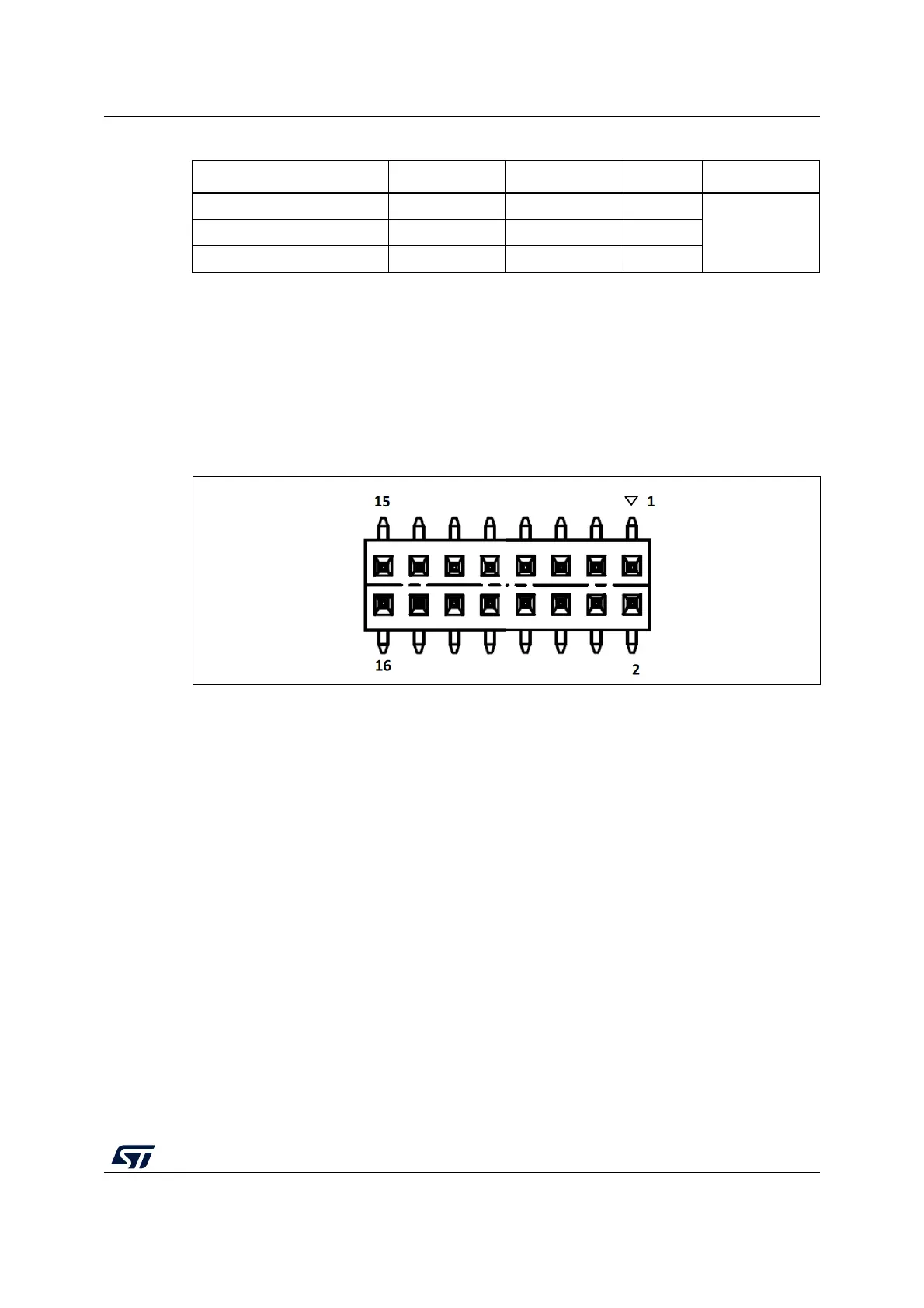
4.13 Extension connector CN12
The extension connector CN12 is a 2.54 mm pitch header located at the bottom side of the
STM32F469I-DISCO Discovery board. It is composed of 16 square pins of 0.64
mm
arranged in double row and it is compatible with usual connectors mating with 2.54
mm
headers, having 0.64
mm square posts. Pins 1, 2, 15 and 16 are marked on the silkscreen
of the PCB, pin 1 is signaled by a triangle as shown below:
Figure 7. Extension connector CN12
The extension connector gives access to the following communication buses and features:
• CAN2
• USART6 (TX, RX)
• I2S2
• SPI1
• 7 timer channels
• 2 ADC inputs
• A 1W monophonic loudspeaker output
• System signals: NRST, MCO1, ANTI-TAMP1
• Power supply: +3V3, GND
The STM32F469NIH6 ports and extension connector pins numbers are detailed in the
following
Table 6: Extension connector pinout:
-PG13D23
CN7 DigitalUSART6_TX PG14 D1 2
USART6_RX PG9 D0 1
Table 5. ARDUINO
®
compatible connectors (continued)
Function MCU Pin Pin name Pin Connector