StoneL publication 105406revA
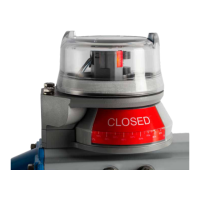
7 QZ 70 en Quartz | 11
Caution: To prevent ignition of hazardous atmospheres,
replace cover before energizing the electrical circuits. Keep
cover tightly closed within operation.
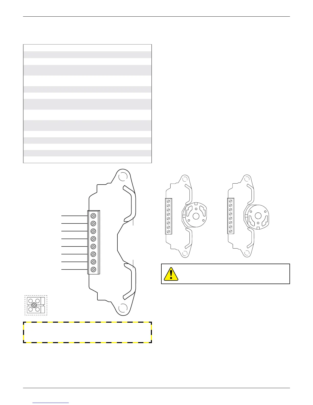
TOP SW LED
(green)
BTM SW LED
(red)
SOL 1
SOL 2
SOL PWR 1
SOL PWR 2
TOP SW NO
TOP SW C
BTM SW NO
BTM SW C
Models with 3 conduit
entries have an additional
2-pole terminal block for
second solenoid termination
Wiring diagram
4.1 Inductive proximity sensors
4.1.2 Dual module SST sensors (35)
Applicable models
QN35_, QX35_
Specications
Conguration (2) Normally open (NO) sensors
Wire terminals for one or two solenoids
Maximum current Inrush 1.0 amp @ 125 VAC/VDC
Continuous 0.1 amp @ 125 VAC/VDC
Minimum on current 0.5 mA (VAC/VDC)
Voltage range 20 - 250 VAC, 8 - 250 VDC
Maximum voltage drop 6.5 volts @ 10 mA
7.2 volts @ 100 mA
Leakage current AC circuits 0.25 mA
DC circuits 0.15 mA
LED indication Bottom sensor: red
Top sensor: green
Temperature range -40° to 80° C
Operating life Unlimited
Warranty
All mechanical parts Two years
Sensor module Five years
Touch & Tune switch setting
All adjustments assume you are looking down on the top of the
sensor module. The magnet in the cam will be centered on the sensor
when activation occurs. When the cam is released be sure it slides fully
onto the spline. One spline tooth setting is 4 ½°.
Valve closed to open in counterclockwise rotation (Fig. 1)
1. With the valve in the closed position, set the bottom cam by lifting
up o the splined collar rotating so that the magnet is centered on
the bottom sensor and the top cam is 90° from the bottom cam.
Top cam is adjusted by pushing down and rotating.
2. At this time the red LED will be lit and green LED out.
3. Move valve counterclockwise to the open position. Green LED
will be lit and red LED will be out. Cam adjustments are now
completed.
Valve closed to open in clockwise rotation (Fig. 2)
1. With the valve in the closed position, set the bottom cam by lifting
up o the splined collar rotating so that the magnet is centered on
the bottom sensor and the top cam is 90° from the bottom cam.
Top cam is adjusted by pushing down and rotating.
2. At this time the red LED will be lit and green LED out.
3. Move valve clockwise to the open position. Green LED will be lit
and red LED will be out. Cam adjustments are now completed.
Bench test procedure
Use StoneL Light Read Tester. Or use a 24VDC or 120VAC power
supply with series load resistor (2k - 6k).
WARNING
Failure to use a series load resistor when bench testing sensors
with a power supply will result in permanent damage to the unit.
Fig. 1 cam set for
counterclockwise
rotation
Fig. 2 cam set for
clockwise rotation
 Loading...