7 QZ 70 en12 | Quartz
StoneL publication 105406revA
4.1 Inductive proximity sensors
4.1.3 SST solid state proximity senors (X)
Bench test procedure
Use StoneL Light Read Tester. Or use a 24VDC or 120VAC power
supply with series load resistor (2k - 6k).
Applicable models
Quartz with 2-wire inductive solid state QN_X_, QX_X_
Specications
Conguration (2) SST solid state sensors
Operation NO/NC (cam selectable)
Maximum current Inrush 1.0 amp @ 125 VAC/VDC
Continuous 0.1 amp @ 125 VAC/VDC
Minimum on current 0.5 mA (VAC/VDC)
Voltage range 24 - 125 VAC, 8 - 125 VDC
Maximum voltage drop 6.5 volts @ 10 mA
7.5 volts @ 100 mA
Leakage current AC circuits 0.25 mA
DC circuits 0.15 mA
LED indication Bottom sensor: red
Top sensor: green
Temperature range -40° to 80° C
Operating life Unlimited
Warranty
All mechanical parts Two years
Sensor module Five years
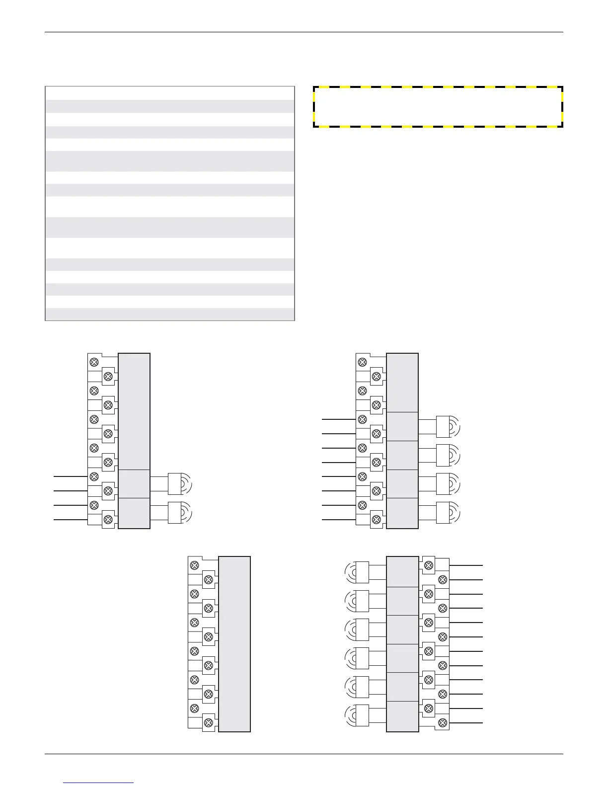
6 SST sensors (QN6X, QX6X)
Wiring diagrams
Unit has 2 vertically
mounted 12-pole
terminal blocks
fourth switch
(red LED)
third switch
(green LED)
second switch
(red LED)
top switch
(green LED)
bottom switch
(red LED)
fifth switch
(green LED)
C
NO/NC
C
NO/NC
C
NO/NC
C
NO/NC
C
NO/NC
C
NO/NC
SPARES
10 12
1
2
3
4
5
6
7 9 11
8
5th SW4th SW3rd SW BTM SW2nd SWTOP SW
C
NO
NCC
NO
NCC
NO
NCC
NO
NCC
NO
NCC
NO
NC
top switch (green LED)
bottom switch (red LED)
NO/NC
C
NO/NC
C
SPARES
1
2
3
4
5
6
7
8
BTM SWTOP SW
C
NO
NCC
NO
NC
third switch (green LED)
bottom switch (red LED)
top switch (green LED)
second switch (red LED)
C
NO/NC
C
NO/NC
C
NO/NC
C
NO/NC
SPARES
1
2
3
4
BTM SW3rd SWTOP SW
C
NO
NC C
NO
NC C
NO
NC C
NO
NC
2nd SW
2 SST sensors (QN2X, QX2X) 4 SST sensors (QN2X, QX2X)
WARNING
Failure to use a series load resistor when bench testing sensors
with a power supply will result in permanent damage to the unit.
 Loading...