StoneL publication 105406revA
7 QZ 70 en Quartz | 21
Applicable models
(QN2G_, QX2G_, QN2H_, QX2H_, QN2S_, QX2S_, QN4G_, QX4G_, QN4H_, QX4H_,
QN4S_, QX4S_)
Specications
Conguration SPDT
Electrical ratings
“G” sensors 0.20 amp @ 120 VAC, 0.30 amp @ 24 VDC
“S” sensors 0.10 amp @ 120 VAC, 0.10 amp @ 24 VDC
“H” sensors* Vmax-240 volts; Imax-3 amps
Wmax-100 watts; Wmin-2.0 watts
Maximum voltage drop No LED
With LED
0.1 volts @ 10 mA
0.5 volts @ 100 mA
3.5 volts @ 10 mA
6.5 volts @ 100 mA
Contact material Rhodium (“G” and “S” sensors)
Tungsten (H sensor)*
Temperature range -40° to 80° C
Operating life 5 million cycles
Seal Hermetically sealed reed switches
Warranty Two years
* Not recommended for electrical circuits operating at less than 20 mA @ 24 VDC
4.3 Reed type proximity switches
4.3.2 SPDT Maxx-Guard proximity sensors (G, H, S)
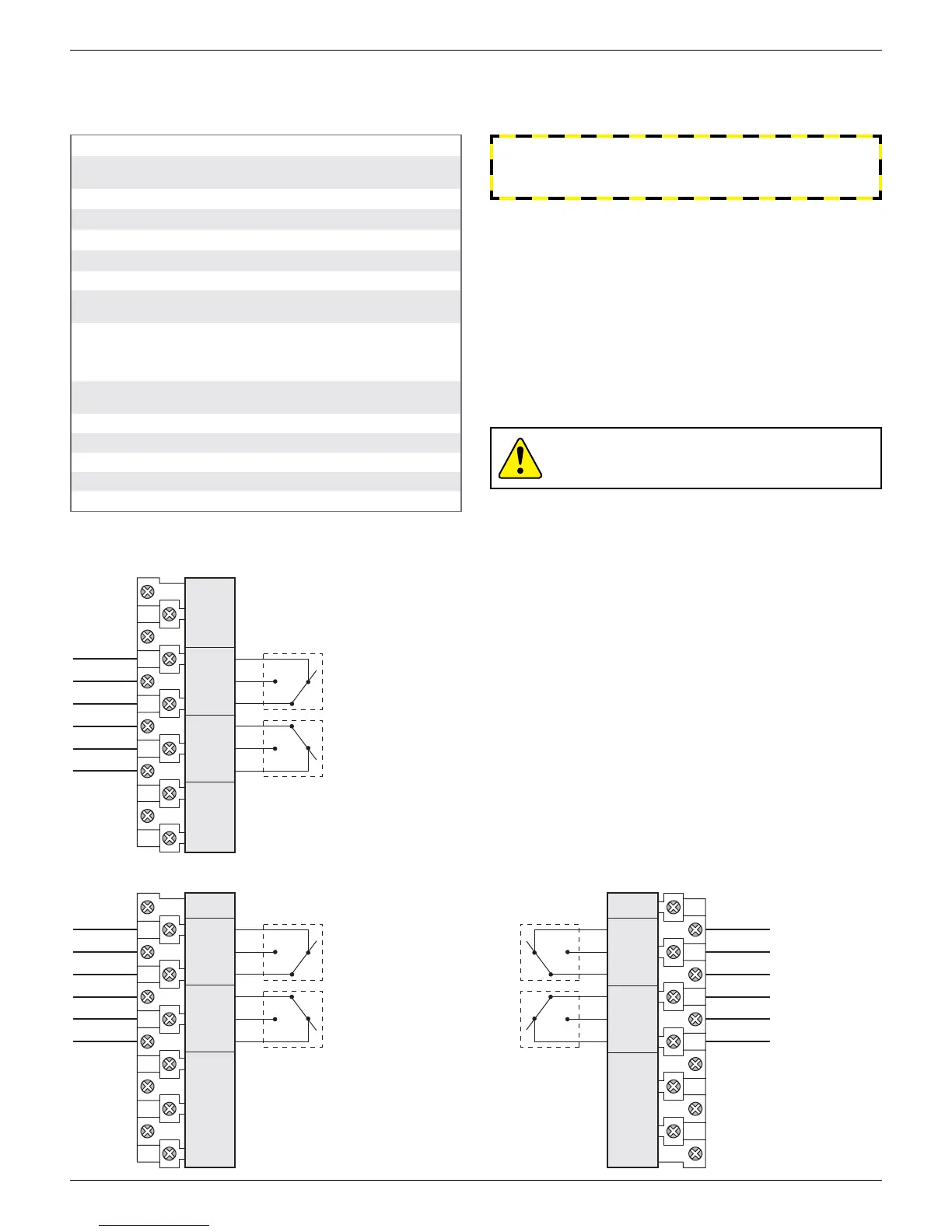
Wiring diagrams
top switch
bottom switch
BTM NC
TOP NC
TOP NO
BTM C
TOP C
BTM NO
SPARES SPARES
1 2 3 4
TOP SW
5 6
NC NCNO NOC C
7 8 9
BTM SW
10 1211
Note: 4 SPDT models have
(2) 12 pole terminal block
(12 spares)
top switch
second switch
TOP C
2nd C
2nd NC
2nd NO
TOP NO
TOP NC
SPARES
1 2 3 4
TOP SW
5 6
NC NCNO NOC C
7 8 9
2nd SW
10 11
third switch
bottom switch
BTM C
BTM NO
BTM NC
3rd C
3rd NC
3rd NO
SPARES
12 13 14 15
BTM SW
16 17
NOC NCCNC NO
18 19 20
3rd SW
21 22
Touch & Tune switch setting
1. Lift bottom cam and rotate until sensor is activated. (White
highlight will be next to sensor.) Release cam and be sure it slides
fully onto spline.
2. Operate actuator to opposite position, push down on top cam and
repeat process.
Caution: To prevent ignition of hazardous atmospheres,
replace cover before energizing the electrical circuits. Keep
cover tightly closed within operation.
Bench test procedure
Test LED units with 9 volt battery and series load resistor between 150
and 1000 ohms - ½ watt. Ohm meter will not work. (Light Read tester
available from StoneL or StoneL distributor.)
Minimum of 3.5 volts required for proper switch operation.
WARNING
Failure to use a series load resistor when bench testing sensors
with a power supply will result in permanent damage to the unit.
2 SPDT switches
4 SPDT switches
 Loading...