7 QZ 70 en8 | Quartz
StoneL publication 105406revA
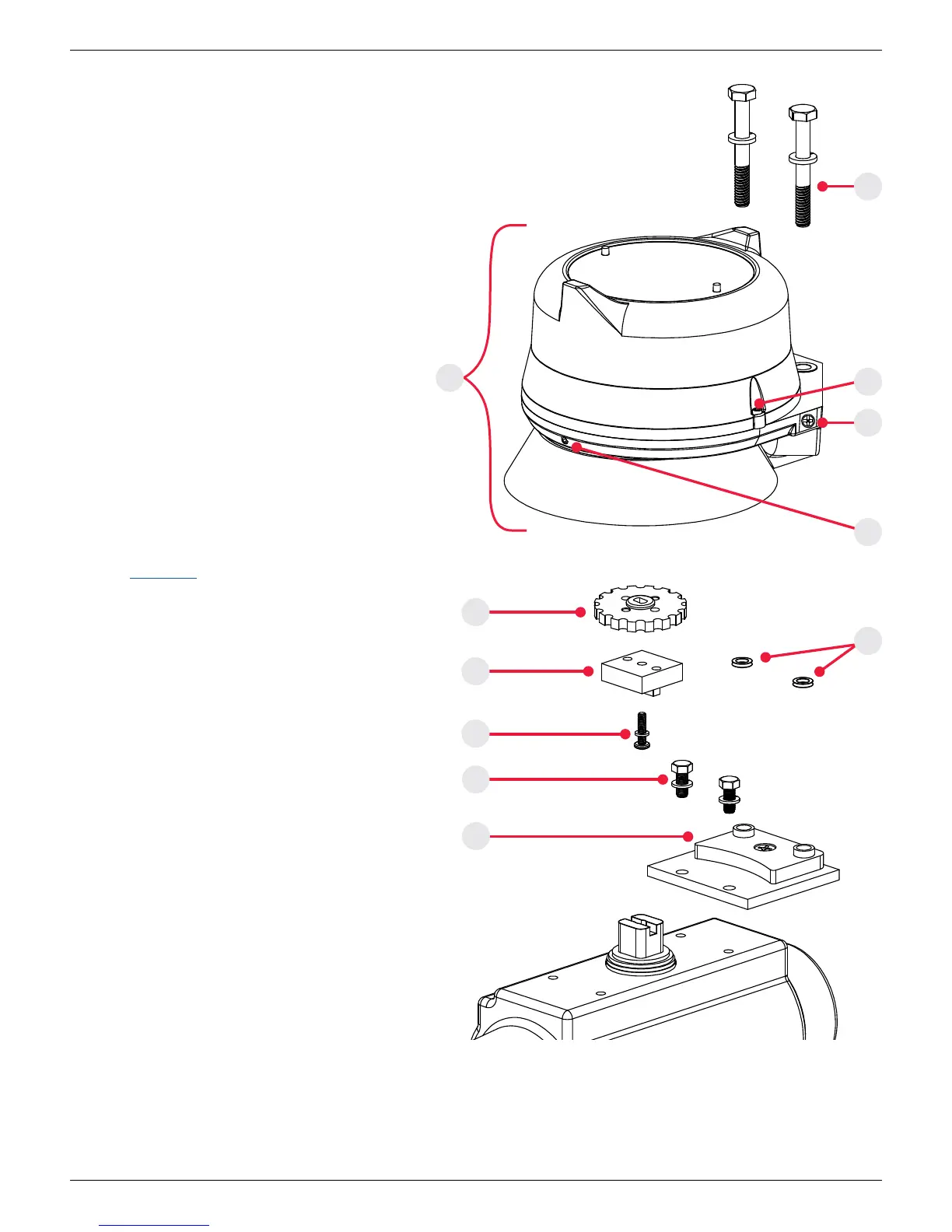
2.3 Typical Quartz with short visual indicator assembly gure
A. Quartz unit
B. Thru-bolt mounting bolts (2)
C. Cover lock (cast cover model only)
D. External ground lug (Internal ground lug provided)
E. Indicator cover setscrew
F. Coupler spacer
G. Thru-bolt retaining o-rings
H. Drive block
I. Drive block retaining screw
J. Mounting plate retaining screws (2)
K. Mounting plate
2.4 Instructions for mounting
with short visual indicator
Special notes:
• Mounting of the Quartz requires a StoneL mounting kit specic
to the actuator the Quartz is to be mounted to.
• It is recommended that thread lubricant or anti-seize be
used on the mounting kit fasteners (Items B, I and J) prior to
assembly.
• In high cycle or high vibration applications, blue Loctite® may
be used on the mounting kit fasteners in place of lubricant or
anti-seize.
• The instructions below are for a typical mounting application.
Refer to StoneL.com for kit specic layout drawings.
Steps
Quartz unit and mounting kit are supplied separately. From Quartz
shipping container, ensure items A and F are present. From the
mounting kit, ensure items B, G, H, I, J and K are present.
1. Locate the mounting plate (ItemK) and place on the actuator.
Using the provided mounting plate retaining screws (Item J),
fasten the mounting plate to the actuator.
2. Loosen indicator cover setscrew (Item E) with an M2 allen
wrench and rotate indicator cover to desired viewing angle
and retighten setscrew.
3. Remove indicator drum screw from Quartz unit.
4. Rotate indicator drum to desired position. (OPEN or CLOSED
appearing through indicator window.)
5. Attached drive block (Item H) to the coupler spacer (Item F)
with the provided drive block retaining screw (Item I).
6. Place Quartz unit onto the mounting plate, ensuring the drive
block tabs engage the slot in the actuator shaft.
7. Slide Thru-bolt mounting bolts (Item B) with washers into
housing and t Thru-bolt retaining o-rings (Item G) over bolts
to retain Thru-bolt mounting bolts in the housing.
8. With an ⁄“ socket, tighten down with the Thru-bolt mounting
bolts. Torque bolts to 15 to 20 in.lbs (1.7 to 2.3Nm).
9. Operate actuator to full open and full closed positions and
check for proper alignment between switch and actuator.
Eccentricity of shaft must not be greater than 0.254 mm [0.1
in] from centerline.
10. Fine-tune the visual indicator cover by repeating steps 2 as
needed.
11. Follow additional Touch & Tune instructions found in section 4
related to the specic model being installed.
J
K
F
E
H
G
I
B
D
C
A
Fig. 2.3 short visual indicator assembly gure
 Loading...