7 QZ 70 en28 | Quartz
StoneL publication 105406revA
4.5 Valve communication terminals (VCT)
4.5.1 VCT with DeviceNet™ communication (92)
Applicable models
QN92_, QX92_
Specications
Communication protocol DeviceNet™
Conguration (2) Discrete Inputs (sensors)
(2) Discrete Outputs (solenoids)
(1) 4-20 mA auxiliary analog input, 10-bit resolution
no additional power source required
Voltage 24 VDC via DeviceNet™ network
Output voltage 24 VDC
Quiescent current 32 mA @ 24 VDC, 48 mA @ 11 VDC
Maximum output current 160 mA, both outputs combined
Maximum output power 4 watts, both outputs combined
Default address 63 (software assigned)
Default baud rate 125K (software selectable 125K, 250K or 500K baud)
Messaging Polling, cyclic and change of state
DeviceNet™ type 100
Bit mapping Inputs (3 bytes)
Byte 0, bit 0 = red LED
Byte 0, bit 1 = green LED
Byte 0, bit 7 = fault bit
Byte 1, bits 8-15 = analog input
Byte 2, bits 16-23 = analog input
Outputs (1 byte)
Byte 0, bit 0 = OUT 1
Byte 0, bit 1 = OUT 2
Byte 0, bit 2 = Wink
Byte 0, bit 3 = not used
Byte 0, bit 4 = not used
Warranty
All mechanical parts Two years
Sensor module Five years
Caution: To prevent ignition of hazardous atmospheres,
replace cover before energizing the electrical circuits. Keep
cover tightly closed within operation.
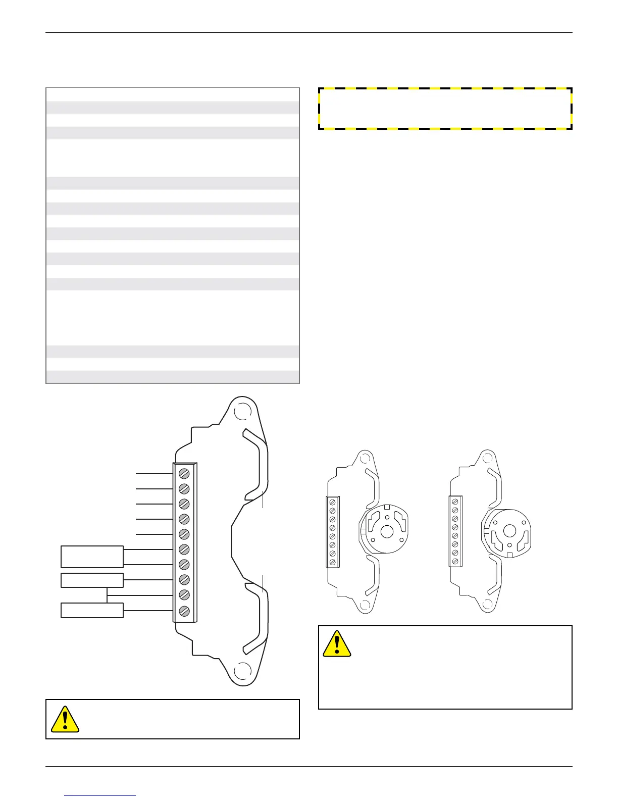
Wiring diagram
TOP SW LED
(green)
BTM SW LED
(red)
V +
CAN_H
Shield
CAN_L
V -
Ain +
Ain -
OUT 1 -
24VDC
OUT 2 -
Solenoid valve*
Solenoid valve*
4-20mA
Transmitter *
*Transmitter and solenoids
not supplied with unit
Bench test procedure
To bench test DeviceNet™ module: Use 24 VDC power supply across
V + and V -. No series resistor needed. To test communication, a
functioning DeviceNet™ network is required.
Caution: To avoid damaging the module when
performing the position switch calibration procedure,
apply 24 - 30 VDC across V + and V -. Use the LEDs to
determine when switches are made. You cannot do this
procedure with an ohmmeter. No series load resistor
is required when attaching a 24 VDC power supply for
switch setting.
Touch & Tune switch setting
All adjustments assume you are looking down on the top of the
sensor module. The magnet in the cam will be centered on the sensor
when activation occurs. When the cam is released be sure it slides fully
onto the spline. One spline tooth setting is 4 ½°.
Valve closed to open in counterclockwise rotation (Fig. 1)
1. With the valve in the closed position, set the bottom cam by lifting
up o the splined collar rotating so that the magnet is centered on
the bottom sensor and the top cam is 90° from the bottom cam.
Top cam is adjusted by pushing down and rotating.
2. At this time the red LED will be lit and green LED out.
3. Move valve counterclockwise to the open position. Green LED
will be lit and red LED will be out. Cam adjustments are now
completed.
Valve closed to open in clockwise rotation (Fig. 2)
1. With the valve in the closed position, set the bottom cam by lifting
up o the splined collar rotating so that the magnet is centered on
the bottom sensor and the top cam is 90° from the bottom cam.
Top cam is adjusted by pushing down and rotating.
2. At this time the red LED will be lit and green LED out.
3. Move valve clockwise to the open position. Green LED will be lit
and red LED will be out. Cam adjustments are now completed.
WARNING
Do not apply power to external power to output terminals as
this will damage the module.
Fig. 1 cam set for
counterclockwise
rotation
Fig. 2 cam set for
clockwise rotation
 Loading...