7 QZ 70 en18 | Quartz
StoneL publication 105406revA
4.2 Intrinsically safe inductive proximity switches
4.2.3 P+F NAMUR sensors NJ2-12GK-SN (A)
Applicable models
QN_A_, QX_A_
Specications
Conguration (2) NAMUR sensors (EN 60947-5-6)
Operation NO/NC (cam selectable)
Current ratings Target present
Target absent
Current < 1.0 mA (LED = OFF)
Current > 3.0 mA (LED = ON)
Voltage range 5 - 25 VDC
Temperature range -40° to 80° C
Operating life Unlimited
Warranty Two years
Use with intrinsically safe repeater barrier. NAMUR sensors conform to EN 60947-5-6 standard.
Touch & Tune switch setting
All adjustments assume you are looking down on the top of the
sensors. The edge of the cam metal strip will be at the edge of the
sensor target when activation occurs. When the cam is released be
sure it slides fully onto the spline. One spline tooth setting is 4 ½°.
Valve closed to open in counterclockwise rotation (Fig. 1)
1. With the valve in the closed position, set the bottom cam so that
the metal activation strip is centered on the bottom sensor target
and the top cam is 90° from the bottom cam. Connect power
supply and ammeter to the bottom switch.
2. Lift up bottom cam and rotate counterclockwise until the
ammeter reads >3mA, then rotate clockwise until the ammeter
reads <1mA. Release the cam.
3. Move valve to the open position. Connect power supply and
ammeter to the top switch. Push down top cam and rotate
clockwise until the ammeter reads >3mA then counterclockwise
until the ammeter reads < 1mA. Release cam.
Valve closed to open in clockwise rotation (Fig. 2)
1. With the valve in the closed position, set the top cam so that the
metal activation strip is centered on the bottom sensor target and
the bottom cam is 90° from the top cam. Connect power supply
and ammeter to the top switch.
2. Push down top cam and rotate clockwise until the ammeter reads
>3mA, then rotate counterclockwise until the ammeter reads
<1mA. Release the cam.
3. Move valve to the open position. Connect power supply
and ammeter to the bottom switch. Lift up bottom cam and
rotate clockwise until the ammeter reads >3mA, then rotate
counterclockwise until the ammeter reads <1mA. Release the
cam.
Fig. 1 cam set for
counterclockwise rotation
top switch
bottom switch
Fig. 2 cam set for
clockwise rotation
top switch
bottom switch
Bench test procedure
Use StoneL Light Read Tester or use a 24 VDC power supply and an
ammeter. No series load resistor required.
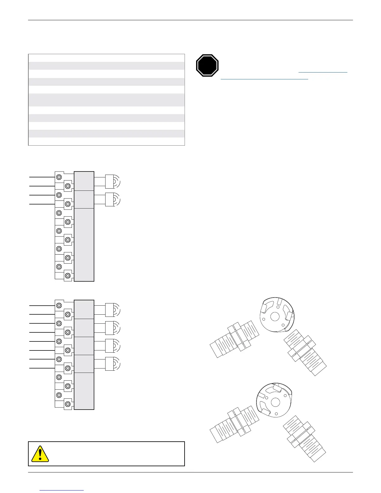
Wiring diagrams
2 NAMUR sensors (QX2A, QN2A)
top switch
bottom switch
TOP SW +
TOP SW -
BTM SW +
BTM SW -
SPARES
1
2
3
4
5
6
7
8
BTM SWTOP SW
-
+
-
+
Caution: To prevent ignition of hazardous atmospheres,
replace cover before energizing the electrical circuits. Keep
cover tightly closed within operation.
top switch
second switch
third switch
bottom switch
TOP SW +
TOP SW -
2nd SW +
2nd SW -
3rd SW +
3rd SW -
BTM SW +
BTM SW -
SPARES
+
-
+
-
1
2
3
4
2nd SW 3rd SW BTM SWTOP SW
-
+
-
+
4 NAMUR sensors (QX4A, QN4A)
Reference controlled installation drawing #105193 for
proper intrinsic safety installation details. Find document
in the Appendix on page49 or at www.stonel.com/en/
products/quartz/installation-manuals
STOP
 Loading...