StoneL publication 105406revA
7 QZ 70 en Quartz | 39
2
1 3
CW
Red/black wire Red/blue wire
Red wire
SPARES
C
C
NO
NC
1
2
3
4
TOP SW BTM SWTRANS
NO
NC
-
+
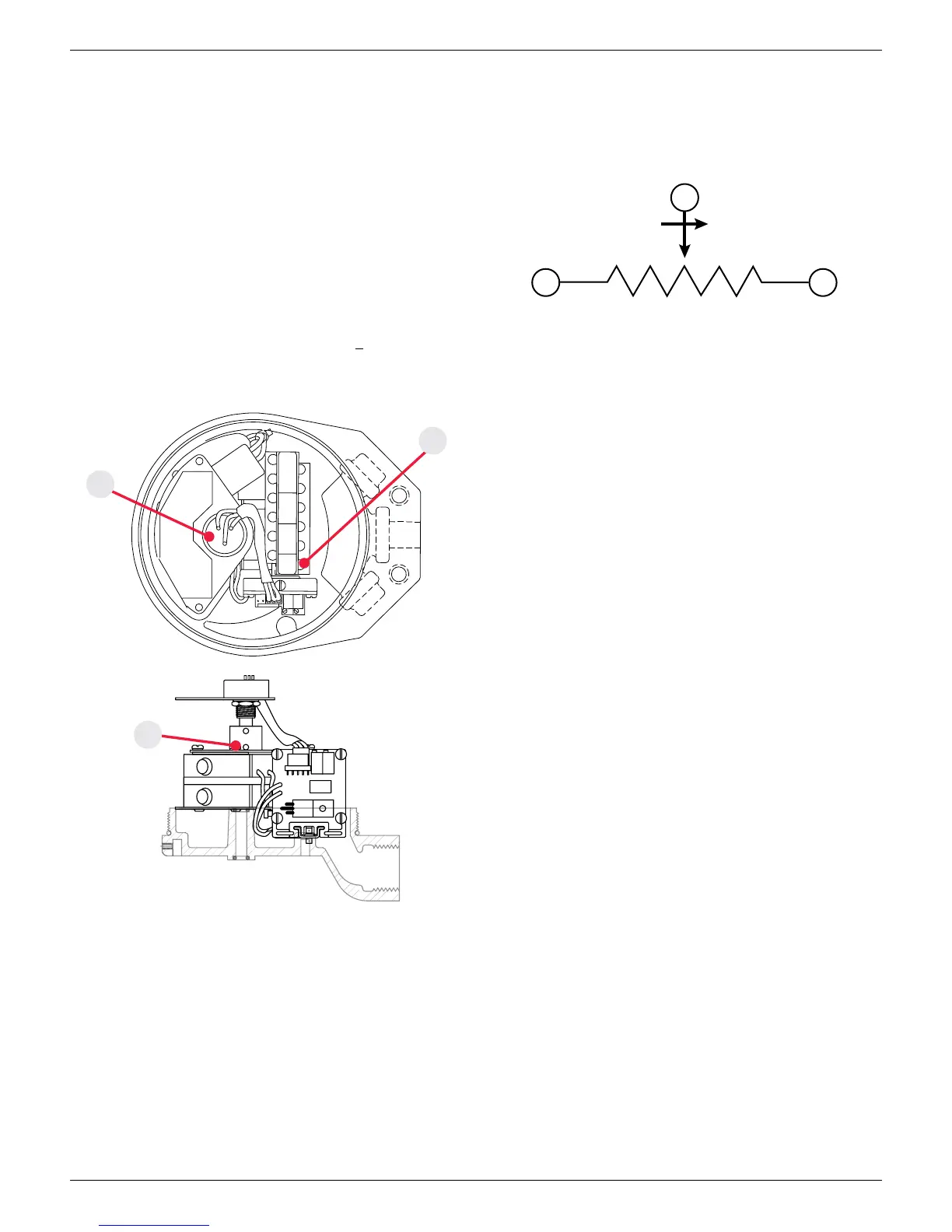
Potentiometer calibration
1. Operate actuator to desired zero position. With power
disconnected, connect an ohmmeter across the terminals located
on top or side of the potentiometer. Refer to electrical schematic.
For counterclockwise rotation (Ohm value to increase), connect to
the terminals with the red lead and red/black lead. For clockwise
rotation, connect the ohmmeter to the terminals with the red lead
and red/blue lead.
2. Loosen bottom set screw and rotate coupling until the ohmmeter
reads < 10 ohms. Retighten setscrew. Verify the ohmmeter still
reads < 10 ohms.
3. Operate actuator to the desired 100% position (assuming 90°
rotation) and verify ohmmeter reads 2.7K ohms + 10%.
4. Remove all test equipment and place unit in service.
4.6.2 Potentiometer with and without switches (Type B_, C_) continued
3
1
4
Electrical schematic
Touch & Tune switch setting
Refer to appropriate installation and adjusting instructions for bench
testing and switch setting procedures for Quartz units with position
transmitter and switches
QNB3, QXB3, QNC3, QXC3 see page10
QNBT, QXBT, QNCT, QXCT see page11
QNBX, QXBX, QNCX, QXCX see page12
QNBE, QXBE, QNBF, QXBF, QNCE, QXCE, QNCF, QXCF see page14
QNB4, QXB4, QNC4, QXC4 see page16
QNBR, QXBR, QNCR, QXCR see page17
QNBA, QXBA, QNCA, QXCA see page18
QNBN, QXBN, QNCN, QXCN see page19
QNBL, QXBL, QNBP, QXBP, QNCL, QXCL QNCP, QXCP, see page20
QNBG, QXBG, QNBH, QXBH, QNBS, QXBS, QNCG, QXCG, QNCH, QXCH,
QNCS, QXCS see page21
QNBJ, QXBJ, QNCJ, QXCJ see page22
QNBM, QXBM, QNCM, QXCM see page23
QXBV, QXBW, QXCV, QXCW see page24
 Loading...