4
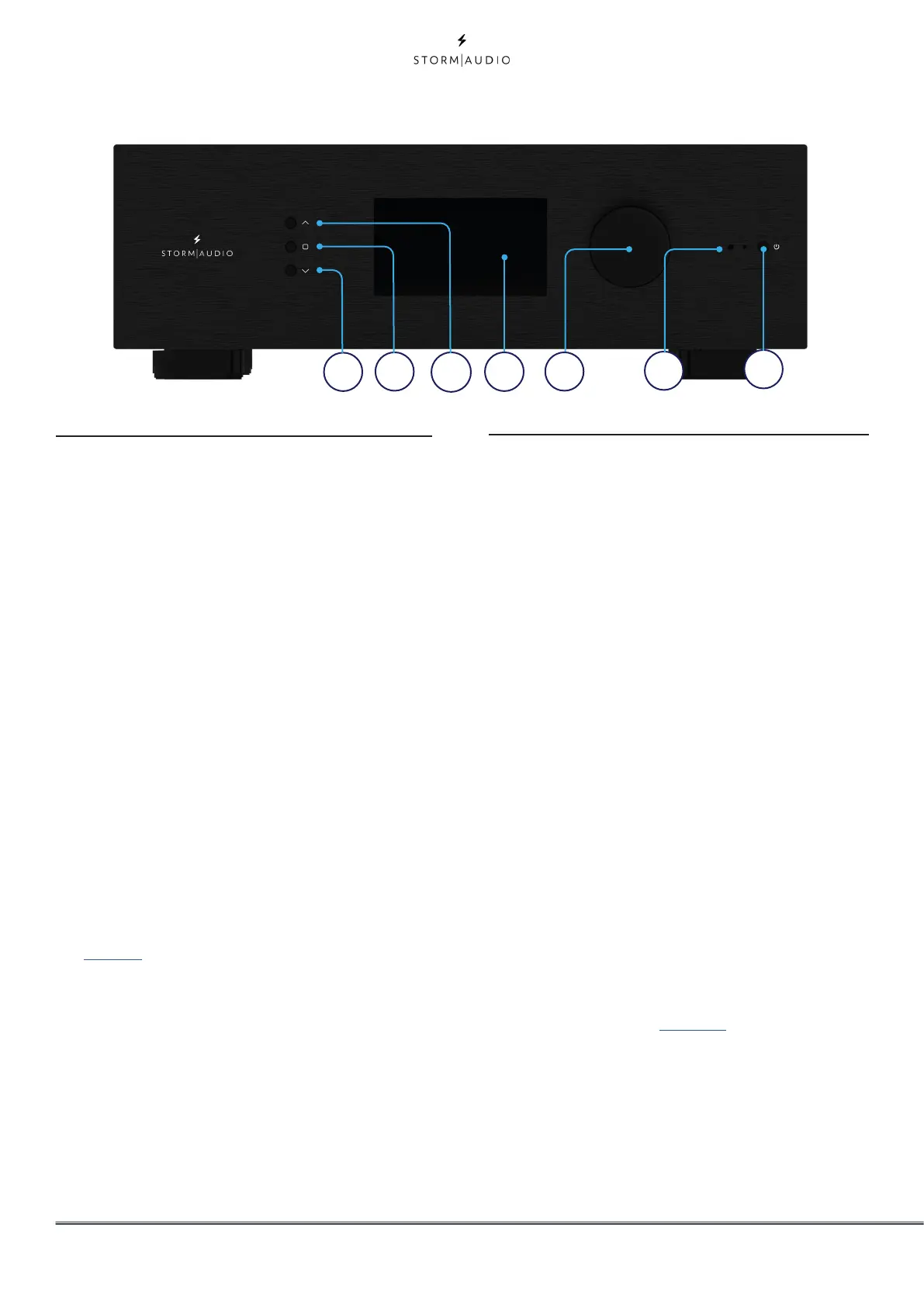
Front panel
1. Power Button
Use this button to toggle the ISP between
ON and STANDBY. Note that the rear panel
switch must be ON for the unit to operate.
2. Down
Use this button to change from Theater/
Zone page or navigate through the Menus.
3. Home / Access
Use this button to access or exit the
Adjustments area and go back to Home
page.
4. Up
Use this button to change from Theater/
Zone page or navigate through the Menus.
5. Display
The front panel display shows various
information about the unit. It is not a touch
screen. Various parameters can be set
according to instructions ”Front Panel” on
page 31.
6. Volume
The default state for the knob is to control
volume in the selected theater. Press
the knob to mute audio. When in the
Adjsutments area, you can use the knob to
change its value. Press to validate.
7. IR Receiver
An InfraRed receiver is located next to the
power button for IR remote control usage.
Rear panel
8. Power Inlet / Fuse Socket / Mains
Switch
Mains power is applied to the ISP here. Ensure
the fuse installed matches requirements of
your locality. The rear panel switch must be
ON for the unit to operate.
9. Network
The ISP must be connected to a network for
setup. It is recommended to be connected
for operation. Speed is 100 Mbps. Use CAT5e
or better cable.
10. USB
Two USB ports are provided to which a USB
microphone may be optionally connected for
RTA function. Or, the USB ports may be used
for service.
11. IR
IR input and output are provided via 3.5mm
jacks for optional control via IR remote.
12. Trigger Out
Four separate trigger outputs are provided to
control power of certain connected devices.
See “Triggers” on page 30 for configuration
information. Each trigger is 12V / 150mA
max. and must not be used for passive daisy
chaining.
13. Digital Inputs
Three Coaxial and 3 TOSLINK Optical digital
inputs are provided for connection of legacy
digital sources.
1
2
3
4
5
6
7