'XFWHGLQGRRUXQLWIRU0XOWLVSOLW5,QYHUWHU
10
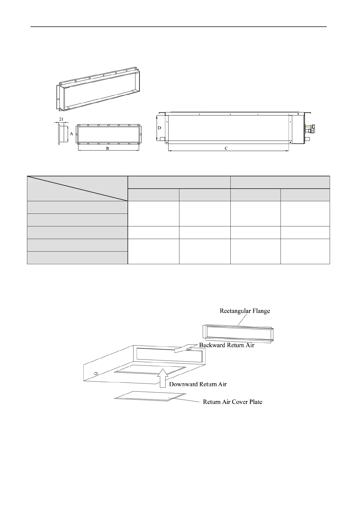
6 Drawings of the Air Supply Outlet and Return Air Inlet
capacity:2.5~7.1kW
Fig.9 Air Supply Outlet Fig.10 Return Air Inlet
Table 4 Dimensions of the Air Supply Outlet and Return Air Inlet (unit: mm)
Air Supply Outlet Return Air Inlet
A B C D
156 662 580 162
156 862 780 162
7 Installation of the Return Air Duct
a. The default installation location of the rectangular flange is in the back and the
return air cover plate is in the bottom, as shown in Fig.11.
Fig.11
b. If the downward return air is desired, just change the place of the rectangular
flange and the return air cover plate.
c. Connect one end of the return air duct to the return air outlet of the unit by rivets