STROBEL
3 Installation
and
putting into service
3.1 Unpacking the machine
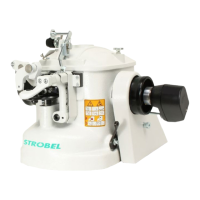
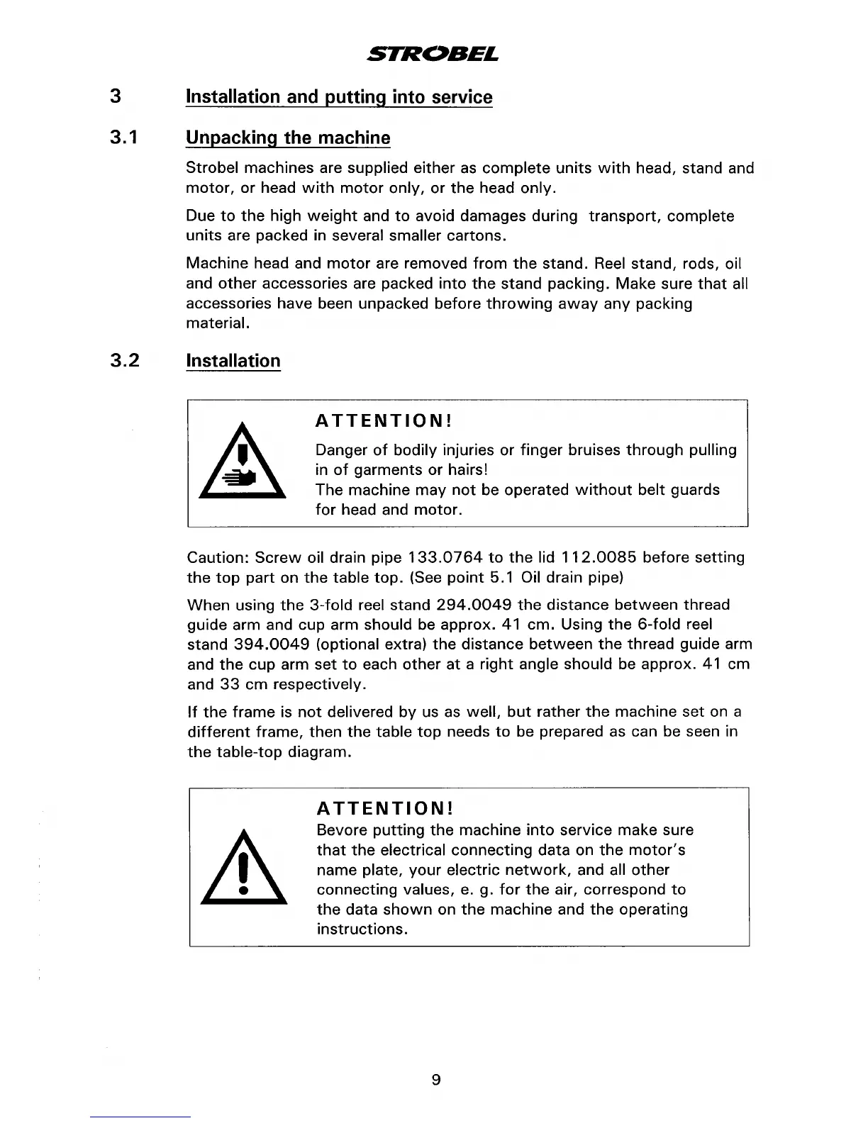
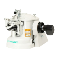
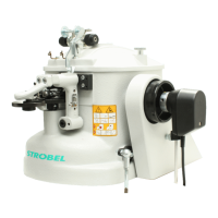
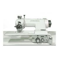
Strobel machines are supplied either
as
complete
units
with
head, stand and
motor,
or
head
with
motor
only,
or
the
head only.
Due
to
the
high
weight
and
to
avoid damages during
transport,
complete
units
are packed in several smaller cartons.
Machine
head and
motor
are removed
from
the
stand. Reel stand, rods, oil
and
other
accessories are packed
into
the
stand
packing.
Make
sure
that
all
accessories have been unpacked before
throwing
away
any
packing
material.
3. 2 Installation
ATTENTION!
Danger
of
bodily injuries or
finger
bruises
through
pulling
in
of
garments
or
hairs!
The machine
may
not
be operated
without
belt
guards
for
head and
motor.
Caution:
Screw
oil drain pipe
133.0764
to
the
lid
112.0085
before
setting
the
top
part
on
the
table
top.
(See
point
5.1 Oil drain pipe)
When
using
the
3-fold
reel stand
294.0049
the
distance
between
thread
guide arm and cup arm
should be approx. 41 em. Using
the
6-fold
reel
stand
394.0049
(optional extra)
the
distance
between
the
thread guide arm
and
the
cup arm
set
to
each
other
at
a
right
angle should be approx.
41
em
and
33
em respectively.
If
the
frame
is
not
delivered
by
us
as
well,
but
rather
the
machine
set
on a
different
frame,
then
the
table
top
needs
to
be prepared as can be seen in
the
table-top
diagram.
ATTENTION!
Bevore
putting
the
machine
into
service make sure
that
the
electrical
connecting
data on
the
motor's
name plate,
your
electric
network,
and all
other
connecting
values,
e.
g.
for
the
air, correspond
to
the
data
shown
on
the
machine
and
the
operating
instructions.
9