Do you have a question about the Stryker L9000 and is the answer not in the manual?
Key safety advice before operating or performing maintenance on the L9000.
Defines symbols used in the manual and on the product for proper usage and safety.
Details factory service and on-site repair options for the L9000.
Outlines necessary skills, tools, and components for performing repairs.
Lists related documents not available for purchase.
Instructions on how to safely clean the L9000 unit and light cable.
Guidelines for proper disposal of the L9000 as electronic waste.
Step-by-step guide for replacing blown fuses in the L9000.
Addresses issues with a loose jaw handle and directs to repair instructions.
Guides on replacing a damaged or rubbing jaw handle.
Troubleshooting steps for a non-functional power button LED.
Steps to address a power button that sticks after being pushed.
Solutions for a blank LCD or unresponsive touch screen buttons.
Explains how to handle console power downs related to "E_" errors.
Troubleshooting steps for a console that fails to power on.
Addresses issues with light emission after cable removal or Standby mode.
Troubleshooting intermittent or flickering light output with Safelight cables.
Diagnosing and resolving issues where light output is not white.
Explains L9000 LCD error codes and recommended actions.
Safety warning about hazardous voltages during AC powered device operations.
Final steps and warnings for adjusting the jaw handle mechanism.
Instructions for removing and replacing the L9000 chassis cover.
Steps for replacing the jaw handle, including Loctite application.
Procedure for replacing the power button and its associated LED.
Continues the steps for replacing the power button and LED assembly.
Final steps for reassembling the unit after power button/LED replacement.
Detailed instructions for replacing the LCD touch screen or front board.
Reassembly steps for the front panel after component replacement.
Procedure for replacing the LED fan assembly in the L9000.
Steps for removing and replacing the AC Inlet Filter.
Guide for replacing the ESST sensor or its contact.
Lists the tools required for final testing and inspection.
Checks for proper fit, clear markings, and damage-free surfaces.
Verifies the console powers on and the light source activates correctly.
Confirms fan orientation and airflow direction.
Tests the functionality of the front panel display and controls.
Verifies the brightness adjustment functionality on the LCD.
Tests the jaw assembly's locking and Standby mode activation.
Procedure for performing a Hi-Pot/Di-Electric breakdown electrical safety test.
Outlines the warranty coverage, exclusions, and claims process.
Explains the procedure for returning products for credit or refund.
Lists required documentation and information for product returns.
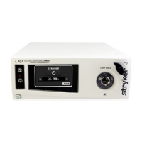
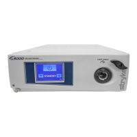
The Stryker L9000 Light Source is a medical device designed to illuminate surgical sites during endoscopic procedures. It utilizes an LED module to generate light, which is then delivered to the surgical site via a fiberoptic light cable. The L9000 is compatible with all Stryker light cables and can connect to most flexible or rigid endoscopes with the appropriate light cable and adapters.
The L9000 is equipped with Electronic Scope Sensing Technology (ESST), a safety feature that helps prevent accidental burns caused by an unconnected light cable. When an ESST light cable, such as a Safelight™, is used, the L9000 detects when the scope and light cable are separated and automatically switches the light source to Standby mode. In Standby mode, the L9000 reduces light output to a minimum, preventing the light cable from generating excessive heat.
To avoid the risk of burns and/or fire, it is crucial to adjust the brightness level of the camera and monitor before adjusting the light source's brightness. The light source brightness should be set to the minimum level necessary for adequate illumination of the surgical site. Adjusting the internal shutter of the camera to a higher setting allows the light source to operate at a lower intensity. Users should avoid touching the scope tip or light cable tip to the patient and never place them on top of the patient, as this can cause burns. Similarly, the scope tip, scope light post, light cable adapter, or light cable tip should never be placed on surgical drapes or other flammable materials to prevent fire. The light source should always be placed in Standby mode when the scope is removed from the light cable or when the device is unattended. It's important to note that these components will take several minutes to cool down after being placed in Standby mode and can still pose a risk of fire or burns.
The front panel features a display that shows "Standby" when the light source is on, along with a brightness display in the bottom right corner. The up/down buttons on the LCD can be used to increase or decrease the brightness number without exiting Standby mode. Pressing the Run/Standby button on the LCD switches the light source to Run mode, with the brightness percentage matching the previously set number. The brightness can be adjusted from 0% to 100% and back without skipping steps.
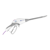
To remove the light cable, the knob on the jaw assembly should be turned clockwise. This action should lock the jaw open, turn off the bulb, and put the light source into Standby mode.
Before cleaning, the L9000 must be unplugged. The external surfaces can be cleaned with a cloth or sponge dampened with a mild detergent or disinfectant. Abrasive cleaners should not be used, and no liquid should be allowed to drip into the unit. The L9000 should never be sterilized or immersed in liquid. The light cable should be cleaned and maintained according to the manufacturer's instructions.
To replace fuses, first unplug the light source from the AC outlet and remove the power cord. Unlatch the fuse holder and remove the fuse(s). Replace the fuse(s) with new ones of the same value and rating (5.0A 250V fuses are specified to avoid fire risk). Finally, reinstall the fuse holder.
The manual provides solutions for common issues such as a loose or cracked jaw handle, power button malfunctions (not lighting up or sticking), and LCD display problems (not displaying or touch screen not activating). Error codes (E-1 to E-5) are defined, with recommended actions ranging from returning the L9000 for repair to replacing specific components like the LED (heat pipe) fan.
Repair and replacement procedures are detailed for various components, including the chassis cover, jaw handle, power button/LED, LCD/front board, LED (heat pipe) fan, AC inlet filter, and ESST sensor/contact. These procedures require specific tools such as Phillips screwdrivers, Allen wrenches, hex wrenches, needle-nose pliers, and Loctite 222.
All repairs should be performed by trained technicians with proper equipment. Dangerous voltages are present in AC-powered devices, and adequate safety precautions must be taken to prevent damage, injury, or death. ESD protection is required during assembly to prevent damage to electrical components. Loctite should be applied to threaded holes rather than screw threads unless otherwise specified.
After maintenance or repair, the device undergoes a series of tests:
The front panel, chassis, and chassis cover should fit snugly without visible gaps. Logos and printing on both the back and front panels should be clear. The jaw handle should turn freely without rubbing against the front panel. All connectors should be properly oriented, and all surfaces should be smooth and free of scratches or dents.
The L9000 should be connected to a 120V power supply. The power button should be pressed to verify that the console powers on. Inserting the light cable into the jaw and pressing the activate button should bring the light source out of Standby mode, and the LED should light up.
Both fan labels should face out, and when the power is turned on, the fans should blow air out the back of the console.
When the light source is on, the display should show "Standby" and a brightness display in the bottom right corner. The up/down buttons should increase/decrease brightness without exiting Standby mode. Pressing the Run/Standby button should switch the light source to Run mode, maintaining the previously set brightness percentage.
The brightness should be adjustable from 0% to 100% and back using the up/down buttons, with the display increasing or decreasing without skipping.
Removing the light cable by turning the knob clockwise on the jaw assembly should lock the jaw open, turn off the bulb, and put the light source into Standby mode.
The Hi-Pot tester should be energized and adjusted to 1.8 kV. The test fixture is plugged into the back of the unit, and an alligator clip is connected to the ground post. The positive (red) probe is touched to the Hi-Pot test fixture, and the test button is pressed for 1 second. The Hi-Pot tester should always be checked for proper functionality before use, and the unit should not be tested for more than 1 second to prevent internal damage.
| Category | Medical Equipment |
|---|---|
| Light Source Type | LED |
| Power Supply | 100-240 VAC, 50/60 Hz |
| Type | Light Source |
| Intensity Control | Adjustable |
| Dimensions | 305 mm x 152 mm x 381 mm |