The Stryker RemB® Electric Universal Driver (handpiece), also known as the RemB Universal Driver, is a medical device designed for a variety of surgical procedures. It is part of the Stryker Consolidated Operating Room Equipment (CORE™) System.
Function Description
The RemB Electric Universal Driver is intended for use in cutting, drilling, reaming, decorticating, shaping, and smoothing bone, bone cement, and teeth. Its applications span orthopedic, dental, ENT (ear, nose, throat), neuro, spine, and endoscopic procedures. It can also be used for the placement or cutting of screws, metal, wires, pins, and other fixation devices. The device operates with Stryker CORE 2, CORE, or TPS Consoles.
Important Technical Specifications
- Model: RemB Electric Universal Driver (REF 6400-099-000)
- Dimensions:
- Height: 5.3 inches [136 mm]
- Width: 1.02 inches [26 mm]
- Length: 5.47 inches [139 mm]
- Mass: 1.18 lb [0.53 kg]
- Speed: 1500 rpm
- Mode of Operation: Non-continuous Operation
- Duty Cycle: 20 seconds on/20 seconds off, 6 times
- Rest Between Cycles: 45 minutes
- Power Supply: 40 V (Direct Current)
- Equipment Type: Type BF Applied Part
- Maximum Temperature of Applied Part: Less than 124 °F [51 °C] (as tested to Product Safety Certification standards)
- Ingress Protection: IPX0 Ordinary Equipment
- Environmental Conditions (Operation):
- Temperature Limitation: 10 °C to 27 °C
- Humidity Limitation: 30% to 75%
- Atmospheric Pressure Limitation: 70 kPa to 106 kPa
- Environmental Conditions (Storage and Transportation):
- Temperature Limitation: -20 °C to 40 °C
- Humidity Limitation: 10% to 75%
- Atmospheric Pressure Limitation: 50 kPa to 106 kPa
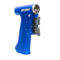
Usage Features
The handpiece features a user-friendly design with distinct controls:
- Release Button (A): Used to release an attachment from the handpiece.
- Attachment Connector (B): The interface for attaching specialized tools.
- Applied Part (C): The distal end of the handpiece and the attachment, which comes into contact with the patient.
- Attachment (D): Various specialized attachments are available for different surgical needs, each with a retainer for wires, pins, tools, or cutting accessories.
- Reverse Trigger (E): A pressure-sensitive trigger for variable speed reverse operation.
- Forward Trigger (F): A pressure-sensitive trigger for variable speed forward operation.
- Cord Receptacle (G): Where the handpiece cord connects.
- Function Switch (H): A three-position switch to control the device's operational mode:
- SAFETY (S): Fully depresses the switch to lock both triggers, preventing accidental activation. This position should always be used when the handpiece is idle, being passed, or when inserting/removing accessories.
- FORWARD (F): Centers the switch to lock the reverse trigger, allowing only forward operation.
- FORWARD/REVERSE (F/R): Fully extends the switch to unlock both triggers, enabling both forward and reverse operation.
- Cord Alignment Mark: A visual indicator for proper cord connection.
To operate, the handpiece requires an attachment to be securely installed by aligning its two J-slots with the attachment connector and pushing until it snaps into place. The handpiece cord connects to the cord receptacle and then to a compatible Stryker console. Operational settings, including oscillate mode and footswitch functions, are programmed via the console touchscreen. Pressure on the triggers controls the speed.
Maintenance Features
- Cleaning and Sterilization: Upon initial receipt and before each use, the equipment must be cleaned and sterilized as indicated in the supplied care instructions manual.
- Inspection: Before each use, all components should be inspected for damage. Damaged equipment or equipment that does not meet inspection criteria should not be used.
- Troubleshooting: The manual provides a troubleshooting guide for common issues:
- Console fails to recognize handpiece or displays error: May indicate incompatible software or an electrical malfunction. Action: Contact Stryker for console upgrade information or return for repair.
- Handpiece will not operate: Could be due to the function switch being in the SAFETY position or an electrical malfunction. Action: Set function switch to FORWARD or FORWARD/REVERSE, or return for repair.
- Handpiece operation is rough or slow: Suggests an electrical malfunction. Action: Return for repair.
- Attachment wobbles: May be caused by improper wire/pin extension, incorrect size, or centering. Action: Reinsert wire/pin; if wobbling persists, return attachment for repair.
- Pin slips in Pin Collet (REF 4100-125-000): Due to design limitations. Action: Use Pin Collet (REF 4100-126-000).
- Function switch does not operate as expected: Incorrect use of switch position symbols. Action: Refer to switch position symbols on the handpiece.
- Attachment difficult to install/interference during installation: Release button mechanism may need lubrication. Action: Refer to care instructions manual.
- Sporadic electrical interference: Presence of electrical noise. Action: Turn off unused electrical equipment, relocate equipment to increase spatial distance, or plug equipment into different operating room outlets.
- Single-Use Devices: Single-use accessories, particularly cutting accessories, must not be reused, reprocessed, or repackaged to prevent contamination, structural integrity compromise, and operational failure.
- Modifications: No equipment modifications are permitted without manufacturer authorization.
- Accessories: Only Stryker-approved equipment and accessories should be used. The handpiece cord (REF 5100-004-000) is sold separately. Earlier versions of Stryker Wire Collet (REF 4100-062-000) or Pin Collet (REF 4100-125-000) with only one J-slot should not be used with the Universal Driver, as it will not fully retain them.