15
Generic Remote Port Routing
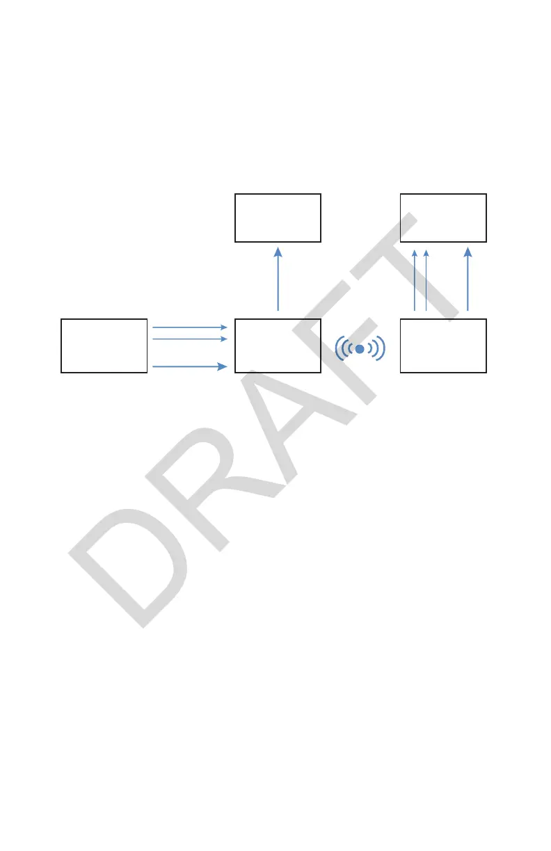
Refer to the following instructions and wiring diagram for a wireless
con guration where the camera control unit is located separately from the
Connected OR Hub.
Note: Obtain a second set of remote cables from another Stryker visualization
system before proceeding.
Camera
Control
Unit
Transmitter Receiver
Connected OR
HUB
HDMI HDMI
HDMI
Remote Cables
Remote
Cables
Display
1. Using the provided HDMI cable, connect the HDMI OUT on the camera
control unit to the HDMI IN on the transmitter.
• The HDMI OUT on the transmitter can be connected to the HDMI IN on
a secondary display.
2. Using a provided remote cable, connect the Remote Out 1 on the camera
control unit to the Remote 1 on the transmitter.
3. Using a provided remote cable, connect the Remote Out 2 on the camera
control unit to the Remote 2 on the transmitter.
4. Using the provided HDMI cable, connect the HDMI OUT on the receiver to
the HDMI IN 1 (4K) on the Connected OR Hub.
5. Using a remote cable, connect the Remote 1 on the receiver to the
Remote 1 on the Connected OR Hub.
6. Using a remote cable, connect the Remote 2 on the receiver to the
Remote 2 on the Connected OR Hub.
7. Link the receiver to the transmitter with the token. (If using a temporary
token, linking is required each time the receiver or transmitter is powered
on.)