Typical Applications
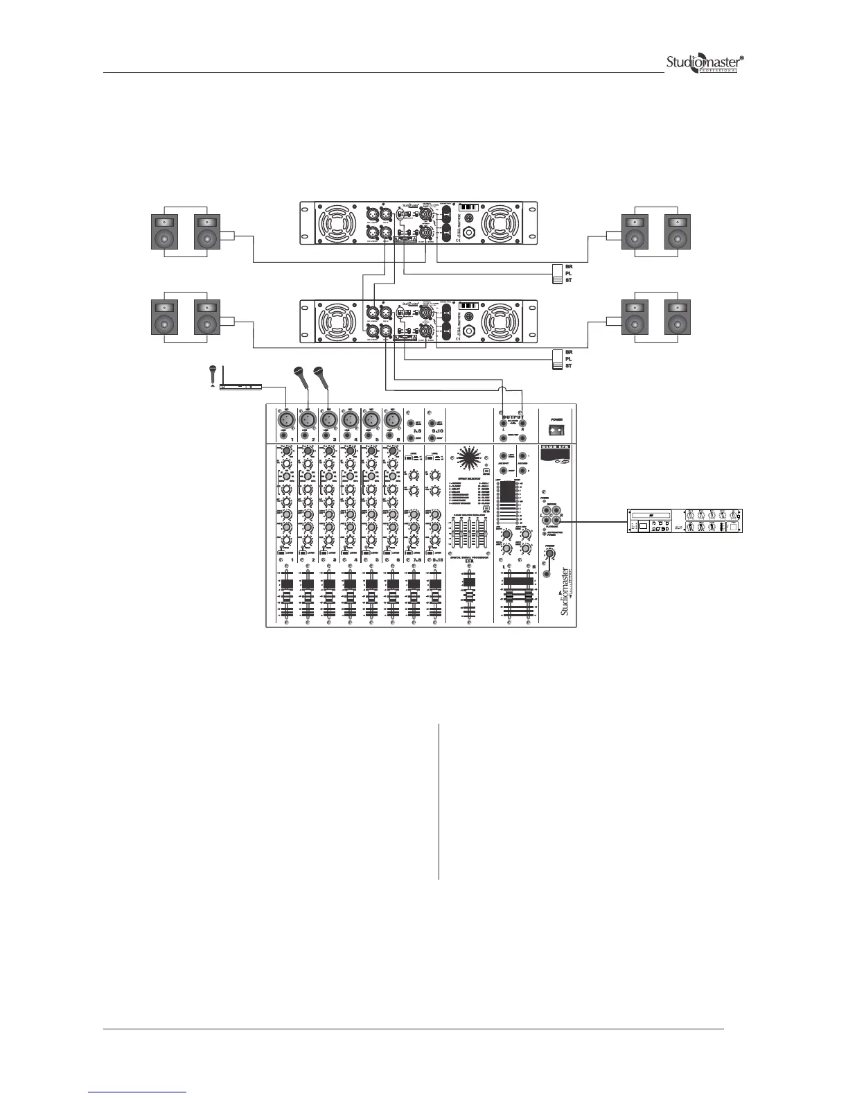
Stereo Mode - Cascade Configuration
Connect the Left and Right outputs of the Audio mixing
console to the channel 1 & 2 (XLR) of amplifier 1.
Connect CH 1 LINK OUT input of amplifier 1 to CH 1 IN
(XLR) of amplifier 2. Similarly make connections for
CH 2.
Speakers can be connected to respective output but
ensure that resultant impedance is not less than 2 ohms.
The input can be wired fig. 1 & 2 (Input Connections for
Balanced and Unbalanced Mode)
The speaker connections of amplifier 2 are done in a
similar way as for amplifier 1.
Amplifier 1 and 2 will be used in stereo mode.
Keep the slide switch of amplifier 1and 2 in stereo
position.
Adjust the volume controls of channel 1 & 2 of both
the amplifiers to control the levels of their respective
Speakers.
Finally any adjustments in the total quantity of the
sound, if required, can be made from the audio
mixing console.
P A MIXER
(Resultant Imp = not < 2Ω) (Resultant Imp = not < 2Ω)
(Resultant Imp = not < 2Ω) (Resultant Imp = not < 2Ω)
AMPLIFIER 2 (Stereo Mode)
AMPLIFIER 1 (Stereo Mode)
MICROPHONES
SERIES
CD PLAYER
WIRELESS
MICROPHONE
15