Typical Applications
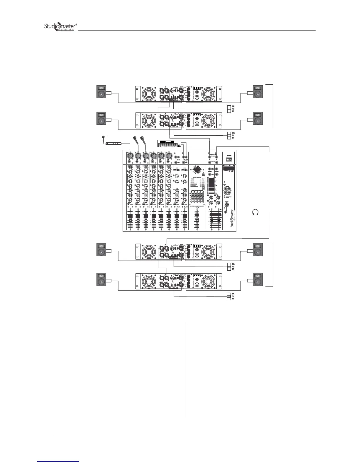
Parallel Mode - High Power Dual Channel Configuration
Connect the left line output of the Audio mixing console to
the channel 1 input (XLR) of amplifier 1.
Connect CH 1 LINK OUT (XLR) of amplifier 1 to the
channel 1 input (XLR) of amplifier 2. The XLR input can
be wired as per fig. 1 & 2 (Input Connections for Balanced
and Unbalanced Mode)
The Left speaker stack compromises of four nos. speaker
systems. Each speaker is individually connected to the four
speaker outputs available from amplifier 1(channel 1 & 2)
and amplifier 2 (channel 1 & 2).
Output speakon connectors to be wired as per fig. 3
(Output Connections for Stereo/ Parrallel Mode) or fig. 5
for Binding Post connection.
Amplifier 1 & 2 will be used in Parallel mode.
Keep the slide switch of amplifier 1 and 2 in Parallel
position.
Similarly, connect the Right line output of the Audio
mixing console to the channel 1 input (XLR) of
amplifier 3. Also connect CH 1 LINK OUT (XLR)
of amplifier 3 to the channel 1 input (XLR) of
amplifier 4.
The Right speaker stack’s connections are done in a
similar way as for left speaker stack’s connections.
Amplifier 3 and 4 will also be used in Parallel mode.
Adjust the volume controls of both the channel in all
the four amplifier to control the levels of their
respective speakers.
Finally any adjustments in the total quality of the
sound, if required, can be made from the audio
mixing console.
P A MIXER
SPEAKER
SPEAKER
SPEAKER
SPEAKER
SPEAKER
SPEAKER
SPEAKER
SPEAKER
RIGHT
BACK
LEFT
BACK
AMPLIFIER 2 (Parallel Mode)
AMPLIFIER 3 (Parallel Mode)
AMPLIFIER 1 (Parallel Mode)
AMPLIFIER 4 (Parallel Mode)
MICROPHONES
SERIES
HEADPHONE
STEREO KEYBOARD
WIRELESS
MICROPHONE
16