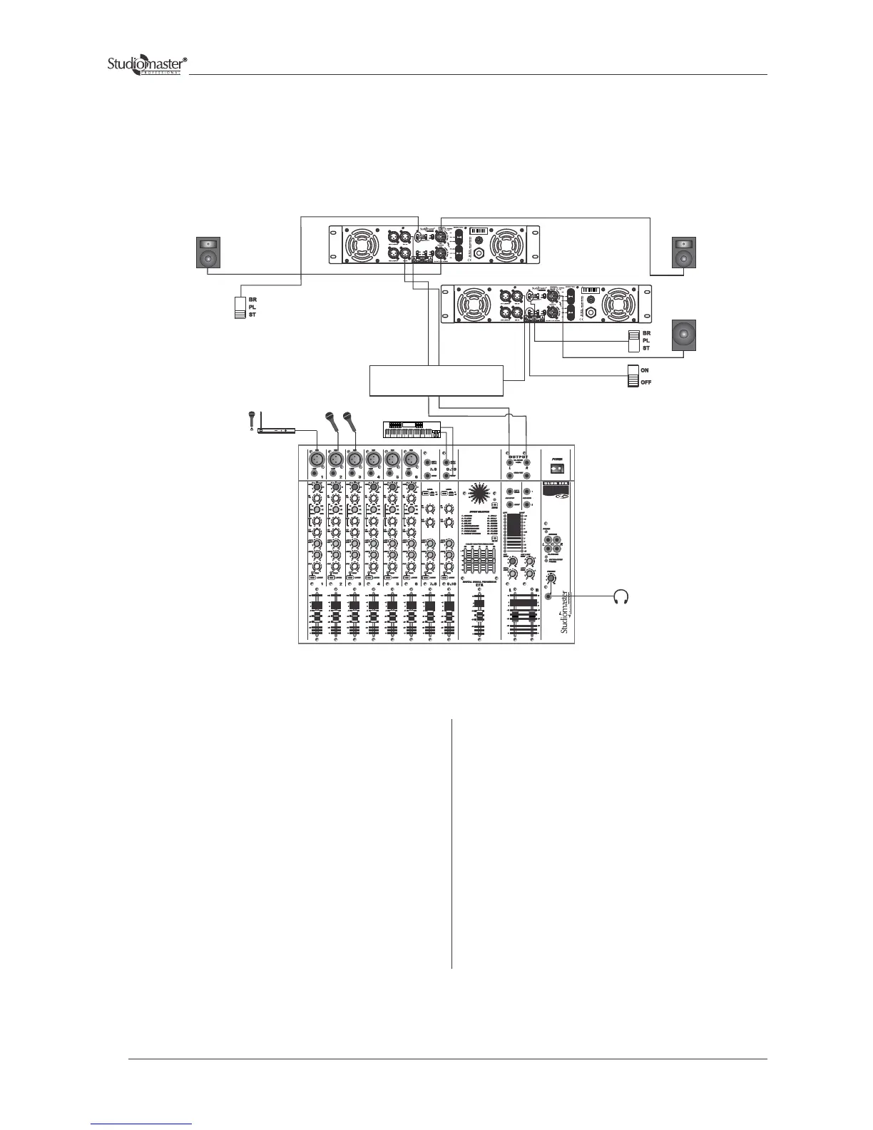
Typical Applications
Stereo Mix Plus Subwoofers
Connect the left and Right outputs of the Audio mixing
console to the respective inputs of the Active Crossover.
Connect the Left and Right High frequency output of the
active crossover to the respective input channels 1 & 2 of
amplifier 1. Inputs can be wired as per fig. 1 & 2 (Input
Connections for Balanced and Unbalanced Mode)
One number of full range loudspeaker system can be
connected to each of the channels of amplifier 1. The
output connectors should be wired as per fig. 3 (Output
Connections for Stereo / Parallel Mode) for speakon or
fig. 5 for Binding Post connections.
Amplifier 1 will be used in stereo mode. Keep the slide
switch of amplifier 1 in stereo position.
Feed the Left low frequency output signal of the crossover
to channel 1 input of amplifier 2. Inputs can be wired as
per fig. 1 & 2 (Input Connections for Balanced and
Unbalanced Mode)
The high powered subwoofer system can be connect-
ed to the channel 1output of amplifier 2. Output
speakon connectors can be wired as per fig. 4 (Output
Connections for Bridge Mode) or fig. 6 for Binding
Post connections.
Amplifier 2 will be used in bridge mode. Keep the
slide switch of amplifier 2 to BRIDGE position to
activate bridge mode as indicated by the glow of
BRIDGE LED, make sure that LOW CUT switch is
in OFF position.
Finally adjust the volume control of channel 1 & 2 in
amplifier 1 to control the level of their respective
position to get desired power. Also, adjust the volume
control of channel 1 in amplifier 2 to control the
levels of their respective position to get desired
power.
P A MIXER
(Fullrange
2/3 way system)
(Fullrange
2/3 way system)
Sub Output
Hi Output
ACTIVE CROSSOVER
Input
Sub Output
(Subwoofer)
MICROPHONES
STEREO KEYBOARD
HEADPHONE
SERIES
WIRELESS
MICROPHONE
30Hz
LOW CUT
AMPLIFIER 1 (Stereo Mode)
AMPLIFIER 2 (Bridge Mode)
14