(© Aug, 2006)
Compact CWE Series Installation, Operation & Maintenance Manual
2-3
NOTE
Equipment must be level to operate properly.
2.4.2 Optional Equipment (Field Installed)
NOTE
Do not mount any optional equipment on unit
access doors.
2.4.2.1 Remote Display
As an option, a factory supplied control panel may be
remote mounted. For mounting and wiring instructions,
refer to the system drawings and the supplemental
manual sent in the data package with your unit.
2.4.2.2 Remote Temperature/Humidity Sensor
The remote temperature/humidity sensor must be
located so that it will properly sense the temperature/
humidity conditions to be controlled. The sensor
should not be mounted near a doorway, near or above
any heat producing equipment or an area where it
would be exposed to direct sunlight. Follow the steps
below to mount the sensor. For unit wiring details,
reference Section 2.7, Utility Connections.
Temperature/Humidity Sensor
1. Using a flat head screwdriver, remove the cover
screw from the top, right corner of the sensor and
remove the cover plate from the base.
2. Place the base temporarily over the wire hole
opening in the wall. Level the base and mark the
location through the two provided mounting slots.
3. Drill the holes and insert the provided wall an-
chors.
4. Place the base over the wires coming out of the
wall and mount with screws provided.
5. Make wiring connections. (See Utility
Connections.)
6. Replace unit cover.
CAUTION
Do not damage the exposed temperature/humid-
ity sensors on the PC board while screwing in
the cover fastening screw. The sensors can be
damaged if handled improperly.
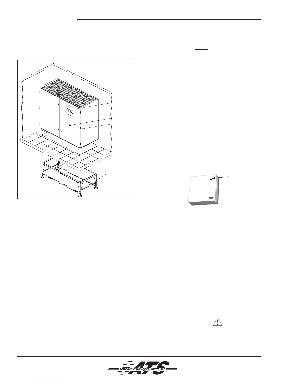
Figure 2- Typical Installation Downflow
OPTIONAL
FLOOR STAND
HINGED
DOOR
(BOTH SIDES)
SERVICE
SWITCH
CONTROLLER
COVER
SCREW