(© Aug, 2006)
Compact CWE Series Installation, Operation & Maintenance Manual
2-7
It is important to verify that the main power supply
coincides with the voltage, phase and frequency
information specified on the system nameplate. The
supply voltage measured at the unit must be within
±10% of the voltage specified on the system name-
plate.
A manual fused disconnect switch or HACR type
circuit breaker must be installed per local and national
electrical codes for service of equipment. Do not
mount a customer supplied manual fused disconnect
switch or HACR type circuit breaker to the surface of
the unit.
Each unit is provided with openings for connection of
the main power and control field-wiring. These open-
ings are located at the bottom of the cabinet. A label
stating "MAIN POWER INPUT" is in close proximity.
Terminate the main power wires at the line side of the
main power disconnect switch located within the
electric box. A separate equipment ground lug is
provided within the electrical box for termination of the
earth ground wire.
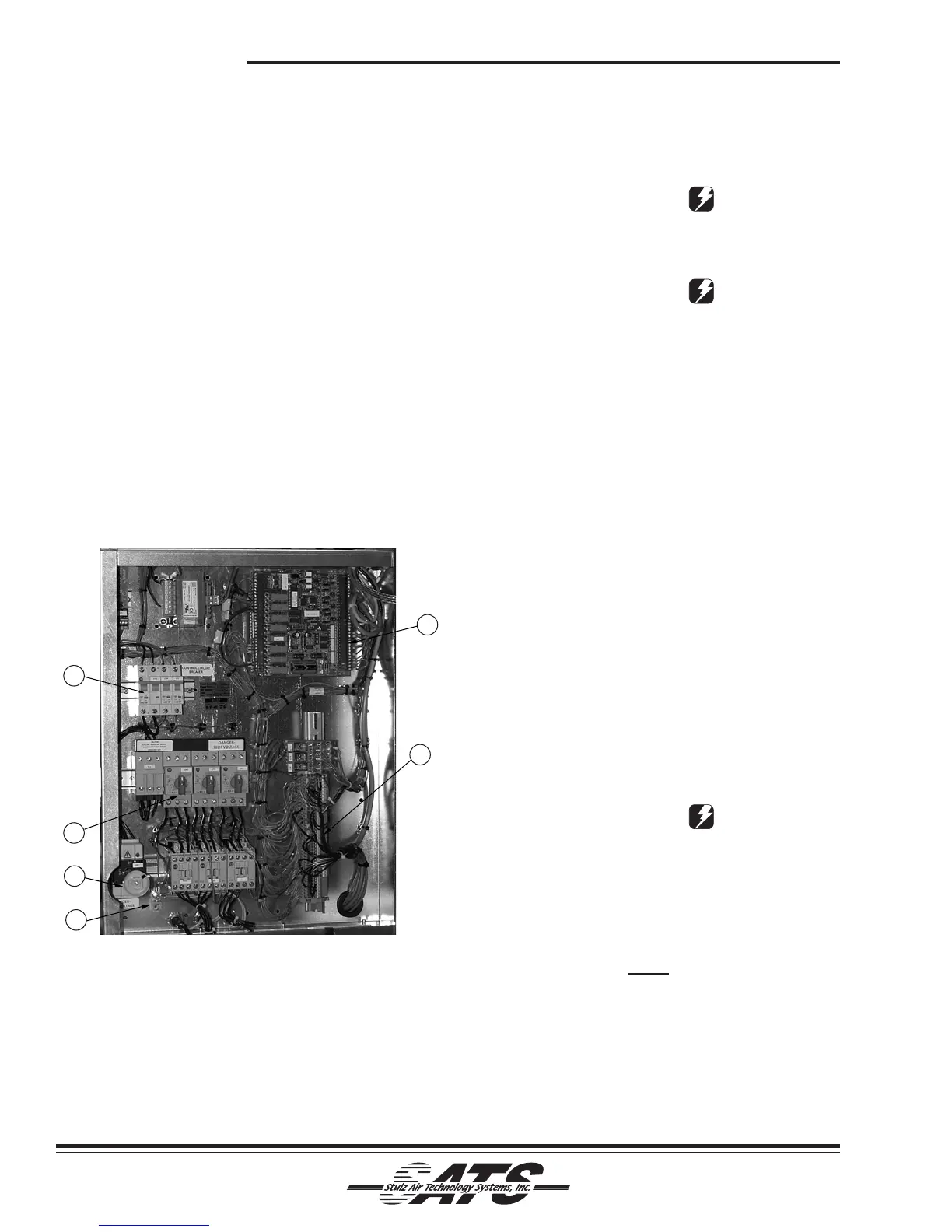
The number callouts in Figure 7 coincide with the
numbered items listed below:
1. Control I/O Board
2. Interface Terminals
3. Main Power Disconnect Switch
4. Ground Lug
5. Power Switches/Motor Starter Protectors
(Quantity varies by size of A/C unit)
6. Control Circuit Breakers
CAUTION
Improper wire connections may result in damage
to the unit.
CAUTION
Prior to unit operation, an adequate unit-to-earth
ground must be connected to the unit.
2.7.2 Controls
Stulz Air Technology Systems offers control features to
solve your air conditioning control/alarm requirements.
The Compact CWE system is furnished with a C6000
Microprocessor controller. If it is mounted on the unit
(standard), no utility connection is required. As an
option a factory supplid display may be remote
mounted. A six-conductor cable harness is provided for
interconnect wiring. Refer to the electrical drawing
provided with the unit for details on interconnecting
field wiring.
2.7.3 Optional Equipment
Additional control conductors may be required depend-
ing on the options purchased with the equipment.
Refer to the electrical diagram supplied with your unit
to determine the total number of interconnecting
conductors required for your system. It is important to
note that the control transformer(s) supplied with the
equipment are sized and selected based upon the
expected loads for each system.
CAUTION
Do not connect any additional loads to the sys-
tem control transformers. Connecting additional
loads to the factory supplied control transformer
may result in overloading of the transformer, which
will cause the transformer circuit breaker to trip.
NOTE
All wiring must be provided in accordance with
local and national electrical code requirements.
2.7.3.1 Remote Temperature/Humidity Sensor
The remote temperature/humidity sensor requires a
three conductor shielded cable, with the shield
terminated at the unit electric box. Both the electric
Figure 7- Electric Box
4
1
3
5
2
6