(© Aug, 2006)
Compact CWE Series Installation, Operation & Maintenance Manual
2-2
2.2 Site Preparation
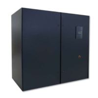
Compact CWE systems are designed with easy
service access in mind. Component access panels are
located on the front of the equipment. The number of
panels may vary depending on size and configuration.
Each unit has one front hinged access panel housing
the electrical box. In order to have full service access
through the front of unit, no permanent obstructions
can be placed in front of the unit. (See Figure 1.)
NOTE
Working clearance requirements need to be es-
tablished prior to mounting the unit. Refer to lo-
cal and national electrical codes.
To minimize the effects of the conditions surrounding
the conditioned space, certain steps must be taken.
This is especially true for critical/precision room
preparation (computer rooms/labs) requiring a close
tolerance of temperature and humidity variation. The
conditioned space should be well insulated and
include a vapor barrier. The installer should ensure that
the proper insulation rating is used based on the
design of the space, which was the basis for the
system selected. The following chart is a recom-
mended minimum R-value (thermal resistance) to
ensure optimum equipment operation.
The vapor barrier is the single most important require-
ment for maintaining environmental control in the
conditioned space. The vapor barrier in the ceiling and
walls can be a polyethylene film. Concrete walls and
floors should be painted with a rubber or plastic based
paint. Doors and windows should be properly sealed
and a door sweep used to minimize leakage. Outside
or fresh air should be kept to a minimum (because it
adds to the cooling, heating, dehumidification and
humidifying loads), while still maintaining the require-
ment of the Indoor Air Quality (IAQ) standard. Lack of
attention to these factors can cause erratic operation,
unstable room control and excessive maintenance
costs.
2.3 Rigging
The Compact CWE systems are designed to be kept
in a vertical position. Move the unit with a suitable
device such as a forklift, pallet jack or roller bar and
dollies. Weight tables are provided on the installation
drawings. Units are shipped on a skid to facilitate
moving prior to installation. Units should always be
stored indoors in a dry location prior to installation.
CAUTION
Units must be kept level and in the vertical posi-
tion when lifting to prevent damage to the unit.
2.4 Mounting/Placement
Compact CWE systems that are not ducted are
designed to be located in the conditioned space.
Ducted units may be located inside or outside the
conditioned space, but are designed to supply air to
only one room. Compact CWE systems are front
accessible, which allows the units to be placed in a
corner or between cabinetry. It is recommended that
the unit is positioned in order to optimize air circula-
tion.
NOTE
Placement of the floor or ceiling registers is im-
portant. If they are too close to the unit, the sup-
ply air will be recirculated back to the unit be-
fore it has circulated throughout the space.
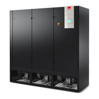
The downflow air pattern A/C unit has been designed
to be located directly on a raised floor. On some raised
floor installations, a floor stand is required, depending
on the load capacity of the existing raised floor. (See
Figure 2).
2.4.1 A/C Unit
The Compact CWE system uses a frame and panel
construction for unit rigidity and full service accessibil-
ity without moving the unit. Ensure the mounting
surface is able to support the weight of equipment.
Before mounting the unit, refer to the weight tables
that are provided in the installation drawings.
If a floor stand is used, refer to the installation drawing
provided and cut out the raised floor to match the
unit’s overall base dimension. If a floor stand is not
used, cut out the raised floor to match blower dis-
charge opening(s) and any required piping and wiring
holes. Refer to the installation drawing supplied with
the unit for dimensional information.
STRUCTURE R-VALUE
Ceiling R-38
Wall R-21
Floor R-19
Door R-5