(© Aug, 2006)
Compact CWE Series Installation, Operation & Maintenance Manual
2-4
2.4.2.3 Remote Water Detector
The remote water detector is normally placed on the
sub-floor or in a field supplied auxiliary drain pan
located beneath the unit. It may be attached using
double sided tape. Prepare surface before installing
tape. Apply tape to the water detector and secure in
place.
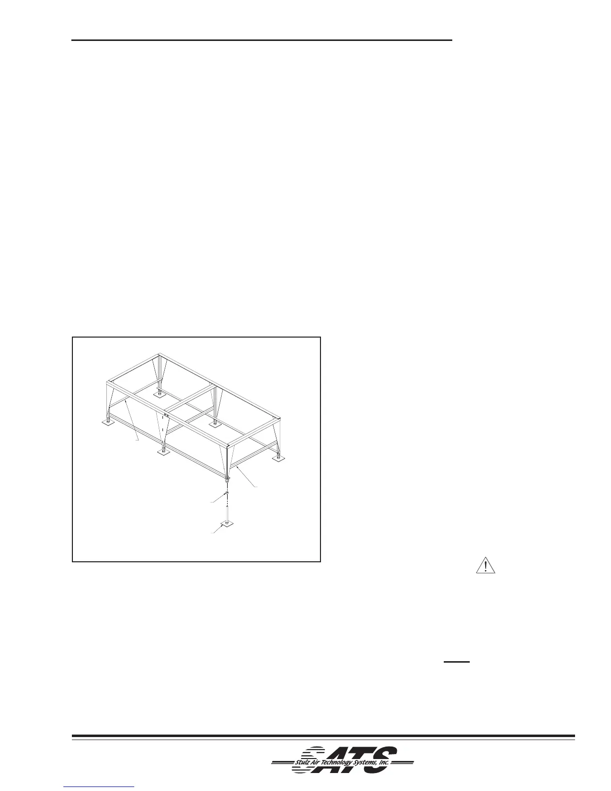
2.4.2.4 Floor Stand
See Figure 3. Install the floor stand directly on the
sub-floor, ensuring the side with the "FRONT" label is
facing the same direction as the front of the A/C unit.
Refer to the installation drawing to cut out the raised
floor. The floor stand is adjustable. Refer to the floor
stand assembly drawing for the minimum and maxi-
mum height of your floor stand. To adjust height, turn
the floor stand foot in the desired direction to raise or
lower the stand. Ensure top of floor stand is even with
the raised floor and level. Lock the feet in place by
tightening the hex nuts against the floor stand legs.
2.4.2.5 Plenum Extension
The optional plenum extension is typically shipped
loose. To install the plenum extension, place the
assembly on top of the unit. Attach with the supplied
self-tapping screws. Holes are pre-drilled in the unit
and the plenum extension box.
2.5 Air Distribution Connection
2.5.1 Downflow Configuration Air Patterns
In a downflow configured unit there are two basic air
patterns: top free return and top ducted return. (See
Figure 4). The conditioned supply air discharges
through the bottom of the unit into the raised floor.
The only air distribution connection required on a
downflow system is on units that require ducting.
When determining ducting requirements, always
consult your local or state codes. The duct system
should be designed to allow the air to move as freely
as possible.
Return inlets are provided with a flange on top of the
unit for connection of the ductwork (refer to the
installation drawing provided with the unit). The
connection of the duct to the unit may be made with
either pop rivets or self-tapping screws.
2.6 Piping Connections
2.6.1 Chilled Water/Hot Water
The openings for the chilled water and optional hot
water reheat piping are located in the base of the unit.
Generally, the piping terminates inside the unit and
uses sweat connections. See the installation drawing
for the exact location of the openings and for pipe
connection sizes.
Pipe should not necessarily be the same size as the
unit connection. Piping should be sized to match the
system pressure drop and flow capacity and may
require a reducing fitting to match the connection size
on the air conditioner. A filling connection and several
shrader valves are installed in the A/C unit. Refer to the
piping diagram supplied with your unit
CAUTION
When installing and filling the chilled water and/
or hot water loops, all air must be bled from the
piping system and the piping system must be
cleaned prior to operating the system. Failure to
do so could result in equipment problems.
NOTE
All chilled water lines must be insulated to
prevent condensation from forming on the pipes.
2.6.2 Condensate Drain
Figure 3- Optional Floor Stand Installation
ONLY REQUIRED ON 24" OR
TALLER FLOOR STANDS
ONLY REQUIRED ON 24" OR
TALLER FLOOR STANDS
HEX NUT
FOOT