(© Aug, 2006)
Compact CWE Series Installation, Operation & Maintenance Manual
2.6.2.1 Gravity Drain
Piping is installed to drain the condensate pan. An “S”
trap is provided at the end of the piping for the installer
to connect a drain line for directing the water away
from the cabinet. This line also drains the (optional)
humidifier. The drain line must be located so it will not
be exposed to freezing temperatures. The drain line
should be the full size of the connection.
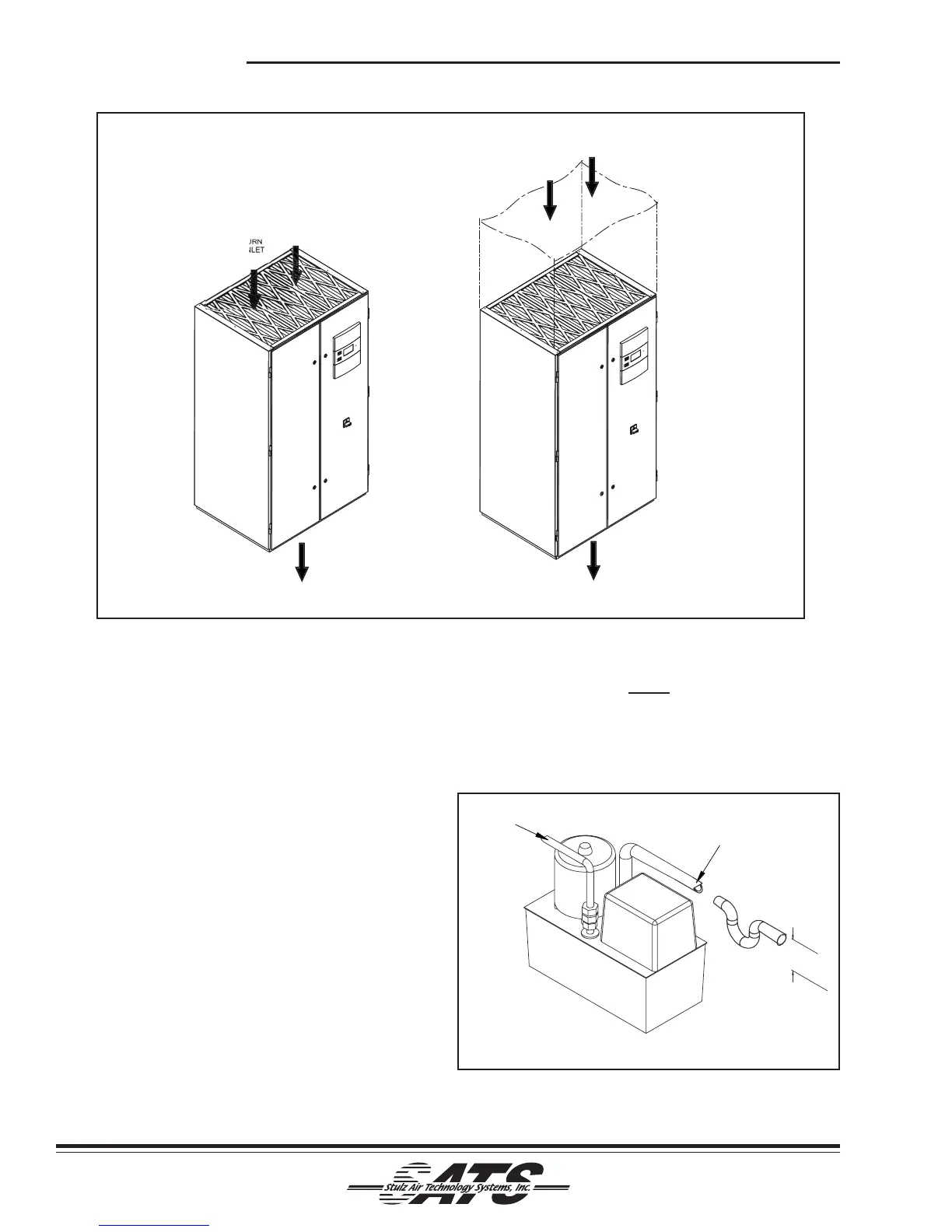
2.6.2.2 Condensate Pump (See Figure 5)
An optional condensate pump may be used for
automatic removal of condensate from the air condi-
tioner and flush water from the humidifier. If an optional
field installed condensate pump is selected, a p-trap
must be installed for proper condensate drainage. The
height of the trap must be a minimum of 2 inches on
most standard systems to ensure proper water
drainage of the drain pan. To prevent excessive back
flow to the unit, the condensate pump discharge line
should be 1/2 inch ID maximum copper or vinyl tubing.
2-5
Figure 4- Downflow Configuration Typical Air Patterns
NOTE
Pour some water into the condensate drain
prior to start-up. This fills the trap and prevents
air from being drawn up the drain line.
INLET 7/8" OD
OUTLET 1/2" OD
NOTES:
1. MIMIMUM HEIGHT IN INCHES.
2. P-TRAP MUST BE LOCATED IN THE INLET SIDE OF PUMP WHEN FIELD INSTALLED.
2.00
SEE NOTE 1
SEE NOTE 2
Figure 5- Condensate Pump
RET
PPLY
AIR
TLE
T
P D
TED RET
RN
T
P FREE RET
RN
ET
RN
PPLY
IR
TLE