22 EN/39B/06.2018 © STULZ SpA – all rights reserved
SAL
4.2. Component lay-out and operating methods
Component lay-out
Internal (evaporator) unit
The air return opening is located in the rear side of the unit. The radial fans are located in the rear
part of the internal unit after the air inlet grille, and, after the entry of the air in the unit, they allow its
blown across the treatment filter and onto the evaporator, exiting from the opening in the frontal
panel or from the opening in the bottom of the unit near the frontal panel (the two panels are
interchangeable).
The electrical box is located in the left side of the unit, between the filter and the fan(s), protected by
an additional metal cover. It contains the electronic controller of the internal unit. Holes for passages
of power supply, signal cables from / to the unit, the plate with signal connectors and refrigerant
connectors to the external unit are located on the rear side, as well as the exit of condensate
drainage pipe. It's possible to install the internal unit also in a vertical position.
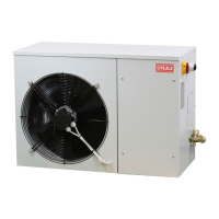
External (motor-condenser) unit
The compressor is located in the right part of the external unit, in an acoustically insulated box,
separated from the condenser part. External air is taken in from an opening on the rear side of the
unit. Then, it crosses condenser just in front of the intake opening and it's expelled from the frontal
grille. Condenser axial fan(s) permitting this circulation is behind the frontal panel and it's accessible
removing the discharge grille on it. The electrical box is under the top panel in SAL size 1, while it's
under the front panel in SAL size 2: in both cases it's protected by an additional metal cover.
Cable entry holes are located on the right side of the unit on the top of the right panel near the
electrical box, and the refrigerant connectors to the internal unit are on the lower part of the right
panel.