26 EN/39B/06.2018 © STULZ SpA – all rights reserved
SAL
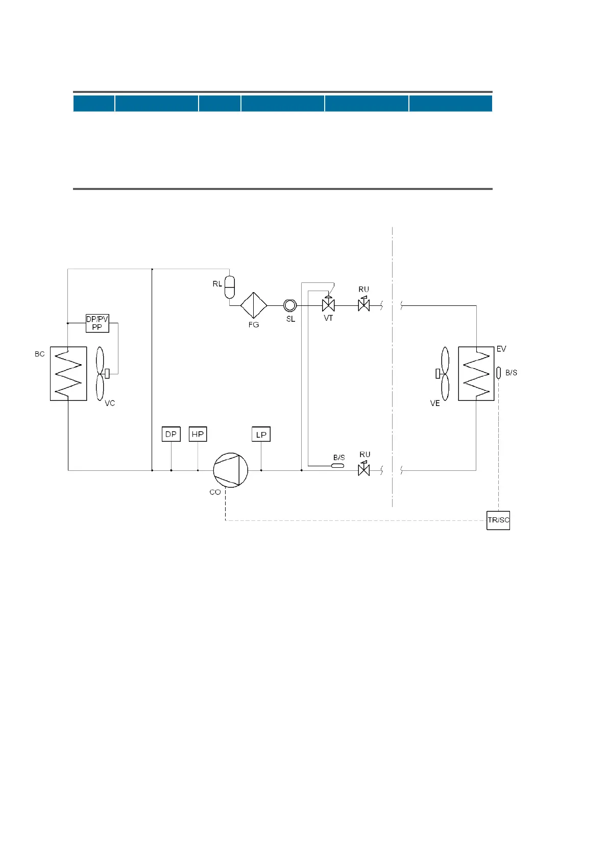
4.3. Refrigerant circuit
Symbol Meaning Symbol Meaning Symbol Meaning
BC Condenser HP High pressure switch SL Sight glass
CO Compressor LP Low pressure switch VC Condenser fan
DP Pressure transducer PV Fan modulation VE Evaporator fan
EV Evaporator RL Liquid receiver VT Thermostatic valve
FG Refrigerant filter
4.4. Cooling components
The refrigeration circuit is open and divided in two parts:
• The motor-condensing external unit includes compressor, condenser, liquid receiver, sight glass,
thermal expansion valve and refrigerant filter. Schrader service valves are fitted internally on the
compressor intake and return lines;
• The evaporating internal unit includes evaporator.
Components of both circuits are connected together by copper piping, appropriately welded to
ensure a greater seal.
The two refrigerant circuits of SplitAir3 internal and external parts must be connected each other
in order to realise a complete hermetic circuit. Copper piping between the two parts have to be
provided by the installer.
During cooling, air inside the room to be conditioned doesn’t mix with external air.
The system works as follows: the compressor compresses the refrigerant gas bringing it to a high
pressure and temperature. The hot gas, by going through the condenser, is cooled and liquefied thus
Outside unit Inside unit