28 EN/39B/06.2018 © STULZ SpA – all rights reserved
SAL
Sight glass
Through the sight glass is possible to see the state of the refrigerant circuit. Bubbles in the sight
glass indicate that the charge is insufficient or that the filter dryer is clogged.
Liquid receiver
The liquid receiver, positioned between the condenser and the condenser fan, keeps the subcooling
level of the refrigerant at a constant level and ensures maximum efficiency over varying operating
conditions. The liquid receiver in SplitAir3 size 1 is 1,3 litres, while in SplitAir3 size 2 is 2,8 litres.
4.7. Mechanical components
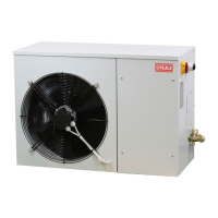
Structure
These machines are built using self-supporting panels made of painted galvanised sheet metal
to guarantee good corrosion resistance (not suitable for corrosive and saline environments). They
make the machine easy to inspect and, at the same time, offer adequate protection to its internal
components. The external panels are internally lined with a 3 mm layer of sound-absorbing material.
The compressor box, in the external unit, is internally lined with a 10 mm layer of sound-absorbing
material. The internal components of the unit can be accessed by simply removing the lower panel.
This is done by undoing their fastening screws.
Air filter
Belonging to class G3, it's designed to prevent large dirt particles present in the environment from
obstructing airflow through the evaporator. It's positioned between the fan(s) and the evaporator.
Condenser water tray
Made of aluminium sheet, it's located under the evaporator to collect the moisture from the internal
air which condenses on the surface of the heat exchanger during cooling. It's provided with a
connector with 16 mm outer diameter for water drain.
INFORMATION
In case the internal unit is installed in vertical position, it's necessary to install the deflector,
which is supplied loose with the internal unit, to collect the moisture. For more information see
paragraph "6.1. Positioning the unit".
Free cooling module (optional)
The free cooling module has to be installed behind the internal unit and it's a metallic frame
containing a metal baffle powered by a servomotor for directing inside and outside air flows. Its body
is made of galvanised sheet metal. Below the technical data of the free cooling module.
Model SFC80 SFCA5
Split unit size SAL406080 SALA0A2A5
Nominal voltage V 48 48
Weight kg 12 17
Height x Width x Depth mm 350 682 310 410 892 370
Inside operating limit temperatures min/max °C -20 / +60 -20 / +60