Component Access & Removal
WARMING DRAWER WWD30
4-5
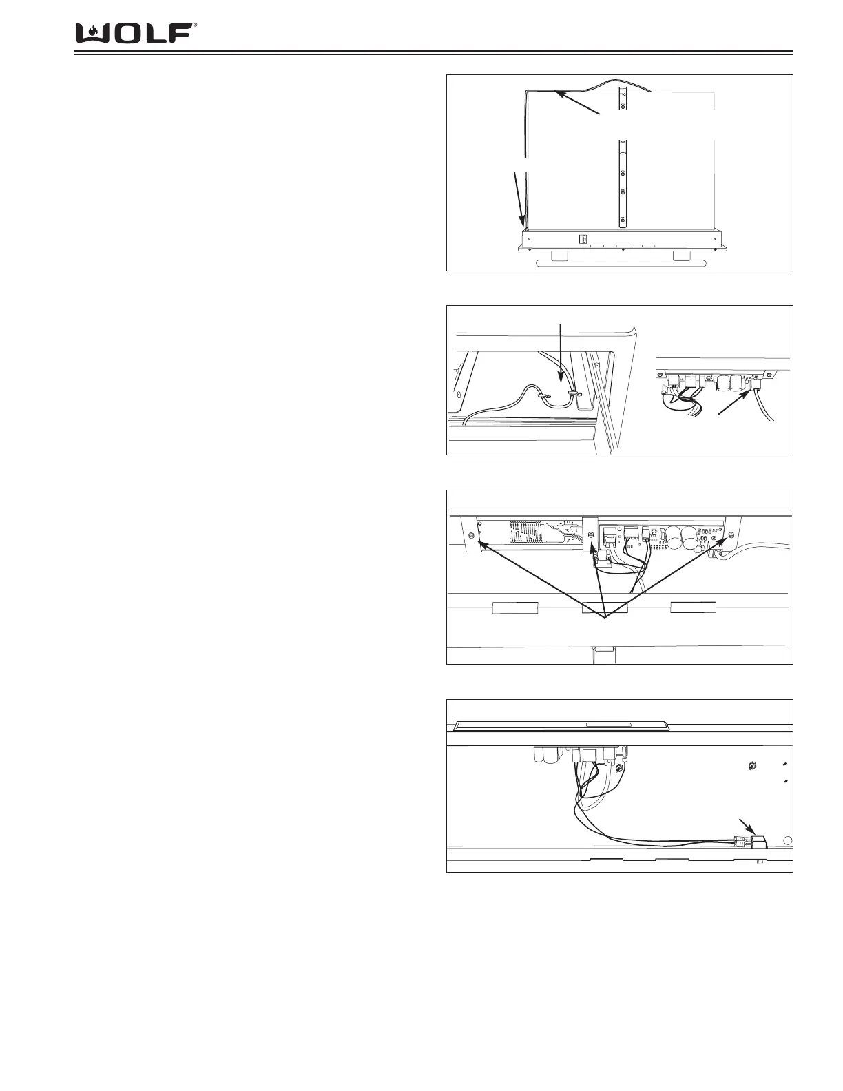
Control Cable Removal
The control cable runs from a jack mounted on the
underside of the control board, through a hole in the
right side of the drawer frame and continuing along the
right side of the drawer, through a cable guard, where it
is secured by retaining clips along the back. From the
drawer, the control cable is routed along the bottom of
unit cavity and is secured by retaining clips. The cable
then continues to the back wall where it plugs into a
jack on the right side of power board.
To remove the control cable, open drawer. Next, remove
front drawer panel and drawer mounting panel. Release
cable from the clips located on the back of drawer. (See
Figure 4-7) Remove the cable guard by extracting the
four nuts securing it to the right side of the drawer. Push
the cable strain relief fitting and control cable through
hole on the right back face of drawer. From inside of
drawer frame assembly, disconnect control cable from
control board. Pull control cable out of drawer assem-
bly.
Control Panel Removal
The control board drops into a slot in the drawer frame
assembly, and has flanges that rest upon the top sur-
face of the drawer frame. From the bottom of the con-
trol panel, screws pass through a bracket and fasten
into the control panel, securing the assembly to the
drawer frame.
To remove the control panel, the front drawer panel and
door mounting panel will need to be removed. Next,
disconnect all electrical leads from control panel. (See
Figure 4-8) Extract the control panel mounting screws
from bracket. (See Figure 4-9) Lift control panel from
drawer frame assembly.
Drawer Switch Removal
The drawer switch is located on the bottom right hand
corner of the drawer frame assembly. The switch con-
trols the heating element and fan operation. A retaining
clip secures the switch to the drawer frame.
To remove the drawer switch, begin by removing drawer
from unit. The front drawer panel and door mounting
panel will need to be removed. From inside of drawer
frame, disconnect electrical leads from drawer switch.
(See Figure 4-10) Depress retaining clip on side of
switch and push through drawer frame.
Figure 4-7. Drawer Bottom with Control Cable
Figure 4-8. Control Cable Hook-ups and Routing
Figure 4-9. Control Panel Removal
Figure 4-10. Drawer Switch Removal
Arrange Control Cable As Shown
Remove Cable From
Under Clip(s)
Hole for Control Cable
Remove Control Cable
From Control Board Here
Remove Screws
Switch