Suburban Dynaline 3 A&E Manual 12/2016 Rev.1
17
Dynaline
™
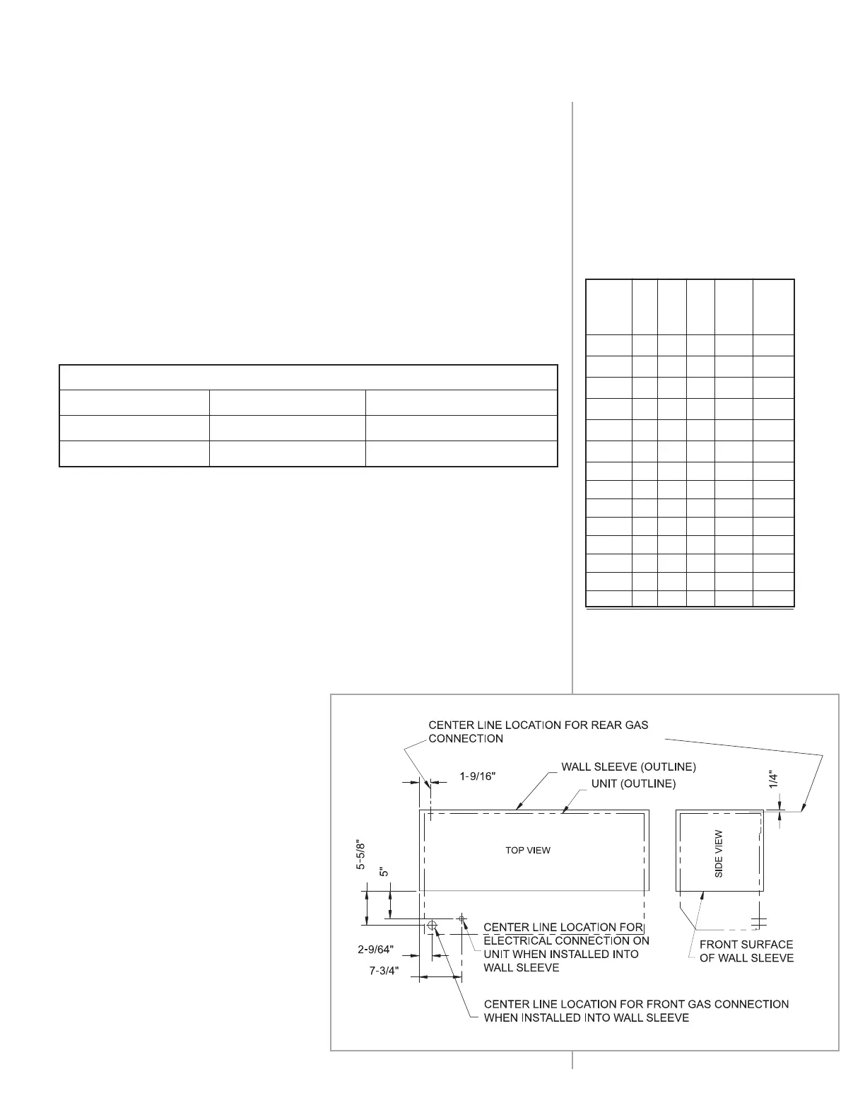
3 chassis are factory equipped with a 3/8" NPT gas connection
located at the bottom left front corner. Gas piping used to make the gas
connection to the unit must be purchased locally. The size of the pipe should be
computed according to type of gas and length
of run. (See
Table 5
.)
See Figure
13 for location of gas connection on the chassis when installed into
the wall sleeve.
Table 5 gives a reasonably accurate size for the gas service line. The quantities in
the table are for cubic feet per hour. To convert BTU capacity to cubic feet, divide
total BTU load by the BTU value of the gas being used. The table is for Natural
gas only. To convert to Propane gas, multiply by .633.
The pressure drop caused by other gas appliances being served must be
considered. If the new line is a take-off from an existing line to another
appliance, pressure drop computation with the table must include the
demand of the other appliance.
Gas supply pressure for purposes of input adjustment
Minimum Maximum
Natural Gas 5" Water Column 7" Water Column
Propane Gas 11" Water Column 13" Water Column
Table 4
Length
of pipe 1/2 3/4 1 1-1/4 1-1/2
in feet
10 132 278 520 1,050 1,600
20 92 190 350 730 1,100
30 73 152 285 590 890
40 63 130 245 500 760
50 56 115 215 440 670
60 50 105 195 400 610
70 46 96 180 370 560
80 43 90 170 350 530
90 40 84 160 320 490
100 38 79 150 305 460
125 34 72 130 275 410
150 31 64 120 250 380
175 28 59 110 225 350
200 26 55 100 210 320
MAKING GAS
CONNECTIONS
Iron Pipe Sizes (IPS) Inches
INSTALLATION DATA
Table 5
Capacity of pipe of different
diameters and lengths in cubic
feet per hour with pressure drop
of 0.3 inches and specific gravity
of 0.60 inches.
All units are equipped with a valve having a built-in regulator. For units
burning Natural gas, the regulator is preset at 3.5" W.C. pressure. For units
burning LP gas, the regulator is preset at 10.5" W.C. pressure.
It is recommended that a shut-off valve be installed in the gas line to
the unit, and that a ground joint union also be installed.
NOTE: Manual shut-off valve to be supplied by installer.
A condensate trap should also be installed in the gas supply line as
close to the unit as possible.
To occasionally monitor the gas
supply pressure to the unit, install a
1/8" NPT plug tap for test gauge
connection immediately upstream
of the gas supply connection to the
unit. The unit must be disconnected
from the gas supply piping system
during any pressure testing of the
gas supply system at test pressures
equal to or greater than 1/2 PSIG.
Figure 13
Operating Pressure
 Loading...