Suburban Dynaline 3 A&E Manual 12/2016 Rev.1
25
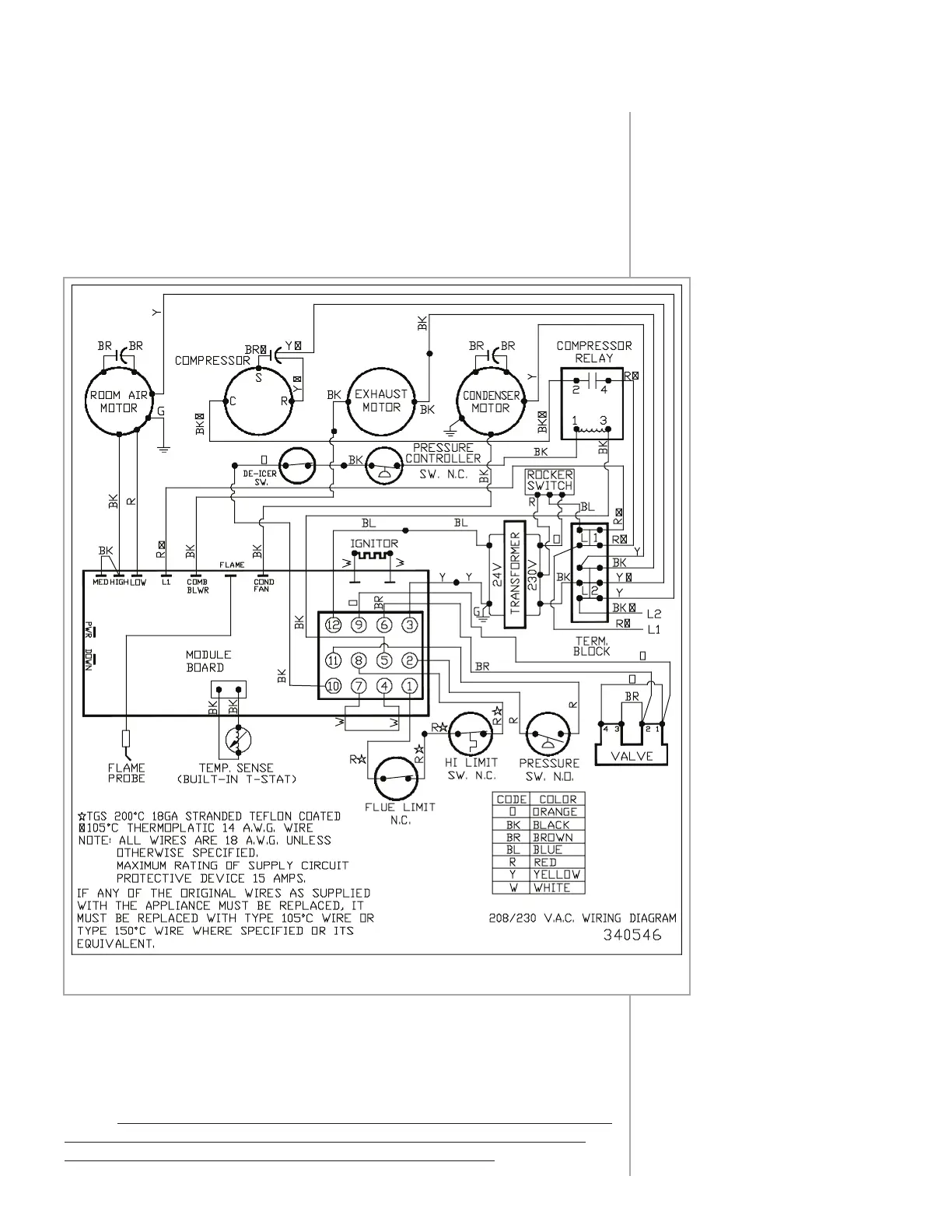
Wiring Diagrams
Schematic: 208/230 V.A.C.
Figure 25
Ladder Diagram: 208/230 V.A.C.
Figure 26
Schematic: 277 V.A.C.
Figure 27
Ladder Diagram: 277 V.A.C.
Figure 28
If local codes permit, the service cord supplied with the unit may be
used for electrical connection. Otherwise, remove the cord and make
electrical connections in the junction box.
All external wiring, including grounding, must comply with local codes
or, in the absence of local codes, with the National Electrical Code ANSI/
NFPA No. 70 (in Canada, with the latest edition of ETL C22.1 Canadian
Electrical Code).
Figure 25
To convert the standard chassis to function with remote thermostat,
connect the thermostat wiring (according to thermostat manufacturer’s
instructions) to the terminal block located on the module board. Move the
dip switch #1 on the module board to the “ON” position. (See Figure 12.)
Unit is capable of operating set-back (5-wire) thermostat.
NOTE: Connecting remote thermostat overrides the built-in thermostat
and no digital read out will be displayed on the control panel. There
is no need to disconnect the chassis’ built-in thermostat.
Schematic:
208/230 V.A.C.
ELECTRICAL CONNECTIONS AND WIRING