Suburban Dynaline 3 A&E Manual 12/2016 Rev.1
14
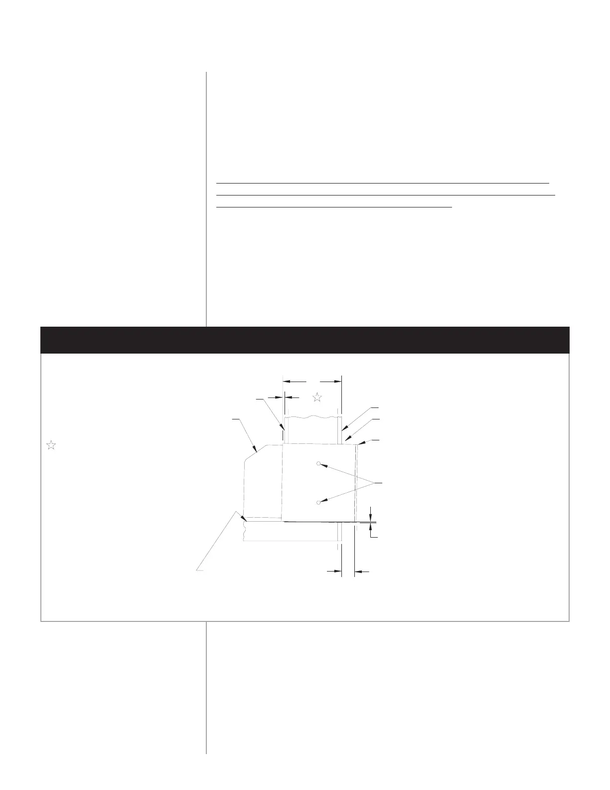
SLOPE DOWN TO THE OUTSIDE
SURFACE OF FINISHED
FLOOR OR TOP OF CARPET
MIN. (PROJECTION BEYOND EXTERIOR WALL)
Y"
X"
MOUNTING HOLES AND SCREWS
(BY INSTALLER.)
DO NOT PUT HOLES THROUGH
WALL SLEEVE BOTTOM!
REAR GRILLE
CAULK AROUND WALL SLEEVE
SURFACE OF FINISHED EXTERIOR WALL
Y" = - ( X" + )
SURFACE OF FINISHED INTERIOR WALL
CABINET FRONT
X" REPRESENTS EITHER THE
DIMENSION REQUIRED TO FLUSH
SLEEVE TO FINISHED TRIM OR
MOLDING, OR THE DISTANCE
SLEEVE PROJECTS INTO ROOM
BEYOND FINISHED INTERIOR
WALL.
NOTE: X" CAN BE 0" IF
SLEEVE IS FLUSH WITH
FINISHED INTERIOR WALL.
1
5
—
8
"
1
—
4
"
1
5
—
8
"
14
3
—
4
"
INSTALLING
THE CHASSIS
1. Slide chassis squarely into wall sleeve from inside and secure with four
(4) screws into flange on wall sleeve to ensure proper security.
2. Connect gas and electrical supply. (See pages 13, 14 and 20.)
3. Remote thermostat: Dynaline
™
3 chassis are supplied for standard
built-in control. To convert the standard chassis to function with remote
thermostat, connect the thermostat wiring (according to thermostat
manufacturer’s instructions) to the terminal block located on the
module board. Move the dip switch #1 on the module board to the
“ON” position. (See Figure 12.) Unit is capable of operating set-back
(5-wire) thermostat.
NOTE: Connecting remote thermostat overrides the built-in thermostat
and no digital read out will be displayed on the control panel. There is no
need to disconnect the chassis’ built-in thermostat.
4. To lock out the A/C compressor when the chassis is powered by
an emergency standby power generator, 24-volt lead wires from the
transformer (NOTE: Field supplied transformer to be powered by the
standby generator) must be connected to the 1/4" spade terminals on
the module board. (See Figure 27 for ladder diagram of typical standby
generator electric service.)
5. Install cabinet front.
Figure 9
WALL INSTALLATION
REAR GAS HOOK-UP