Suburban Dynaline 3 A&E Manual 12/2016 Rev.1
20
DL3-1220/DL3-1622 DL3-0912**
1* 2 3 3
HI LOW HI LOW HI LOW HI LOW
50/50 143/121 127/108 50/50 144/122 128/108 50/50 145/123 129/109 50/50 123/104 109/93
60/40 159/102 142/91 60/40 160/103 143/91 60/40 161/103 143/92 60/40 137/88 122/78
70/30 173/85 154/76 70/30 174/84 155/76 70/30 175/86 156/77 70/30 149/73 132/65
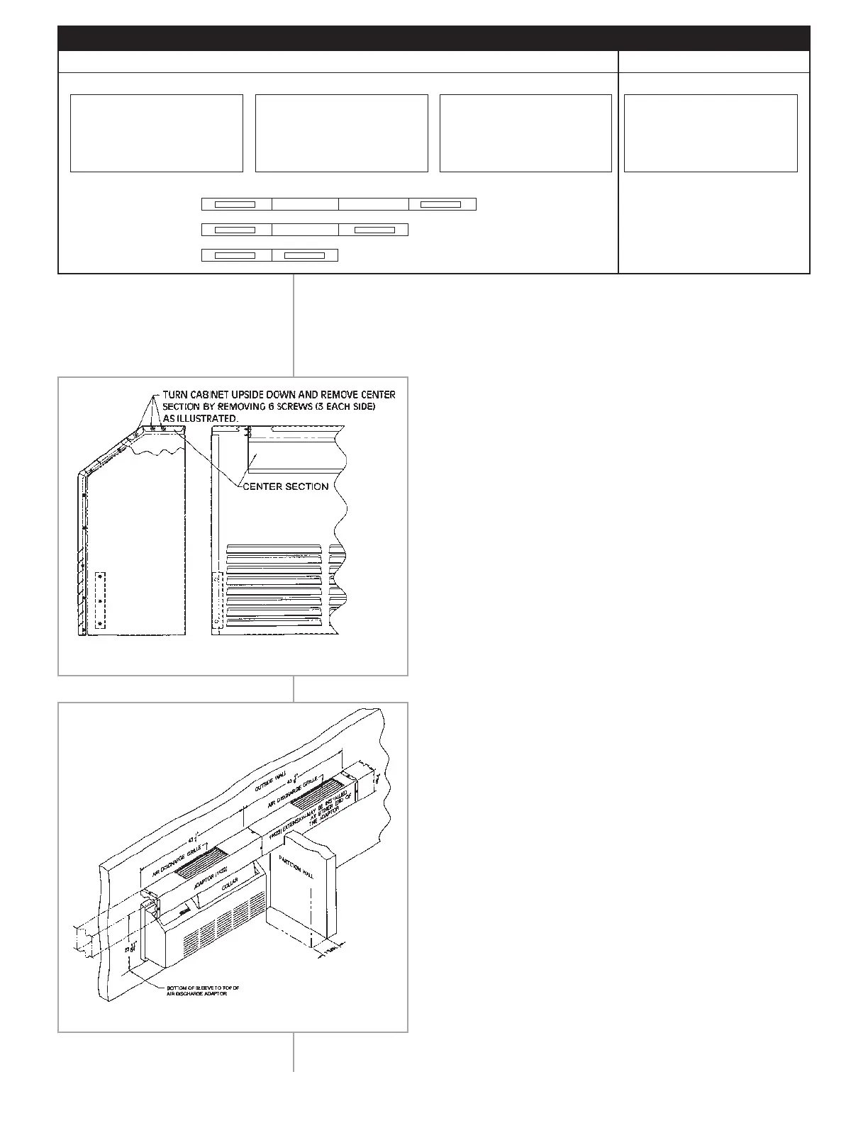
Installation when adaptor support brackets are mounted
to finished wall.
NOTE: Projection of wall sleeve into room cannot exceed 1-1/4".
1. Mount adaptor brackets to the wall as illustrated.
Installer to provide screws. (See Figure 17.)
2. Slide collar into position under the adaptor and secure
with the two (2) screws provided. (See Figure 16.)
3. If the required air flow direction is to the left, remove
the end cap and three (3) tinnermans from the left end
of the adaptor. Reinstall end cap and tinnermans to
the right end of the adaptor.
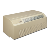
4. Remove the center section from the cabinet front
assembly. (See Figure 15.) If the center section is not
removed, you will be unable to open the cabinet
front once the collar and adaptor are installed.
Discard center section.
5. Remove the discharge air grille from the unit.
Retain the two (2) screws.
6. Place the adaptor and collar assembly into position
on the unit. Make sure the adaptor is resting on the
adaptor brackets – adjust brackets as needed!
7. Locate the hole in the adaptor bracket and mark the
underside of the adaptor at each end.
8. Remove adaptor and collar assembly from unit. At the
two (2) locations marked on the adaptor in Step #7,
drill a 7/64"-diameter hole (2 places).
9. Install adaptor and collar assembly on unit as
illustrated and secure with the two (2) screws retained
in Step #5. Also, secure the adaptor to the adaptor
brackets with the screws provided.
10. Install the extension (DL3-0912) or the connector(s)
and extension (DL3-1220 or DL3-1622 only) as
required. Installer must provide wall support brackets
for the connectors and extension.
11. Air Delivery: The air delivery baffle, located under the
discharge air grille in the adaptor, is factory positioned
to provide a 50/50 distribution of air into each zone.
By removing the baffle and cutting along the scored
line, 60% of the conditioned air will flow in the
primary zone. Removing the baffle results in a 70/30
split. (On model DL3-1622 you must remove the
baffle). For best results unit should be run on Hi only
when using discharge package.
CFM CHART (DRY COIL)
** DL3-0912 - 1 and 2
are N/A. There is only one
extension or connector
allowed for DL3-0912
INSTALLING AIR
DISCHARGE PACKAGE
Figure 16
Figure 15
* Max. length = 130" from adaptor.
1
2
3
A
A
A B
B
B
Table 6
 Loading...