Section 6
MAINTENANCE
28
046782, and follow the instructions below for proper
installation.
1. Remove the four (4) screws which hold the assem-
bly together.
2. Pull the top cover away from the body.
3. Remove the old gasket and o-ring and replacewith
the new ones.
4. Align the top cover with the body, replace the four
(4) screws and tighten.
PILOT VALVE MAINTENANCE
Refer to Figure 6-13. Pilot valve (P/N 250017-993)
maintenance is quite minimal but a periodic cleaning
is desirable. Thetime between cleanings will vary de-
pending on operating conditions. In general, if the
voltage to the coils is correct, sluggish valve opera-
tion or excessive leakagewill indicatethat cleaning is
required. If parts replacement is required, order re-
pair kit No. 250018-970or 250018-971and follow the
procedure explained below:
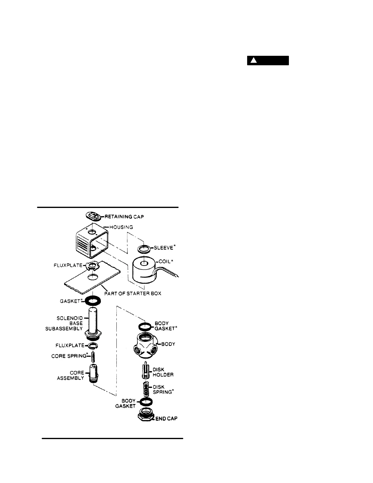
Figure 6-13 Pilot Valve (P/N 250017-993)
* Repair Kit P/N 250018-970 (valve)
** Repair Kit P/N 250018-971 (coil)
WARNING
!
Turn off all power, relieve line pressure, and dis-
connect coil lead wires to the valve before making
repairs.
It is not necessary to remove the valve from the pipe
line for repairs.
DISASSEMBLY AND REASSEMBLY
1. Remove the retaining cap and slip the entire sole-
noid off the solenoid base subassembly.
2. Unscrew the solenoid base assembly. Remove
the core assembly, core spring and body gasket.
3. Next, remove the end cap, body gasket, disc
spring, and disc holder assembly.
4. All parts are now accessible for cleaning or re-
placement. Replace worn or damaged parts with
repair kit No. 250018-970 for best results.
5. Reassemble in reverse order of disassembly.
COIL REPLACEMENT KIT (P/N 250018-971)
1. Remove the retaining clip.
2. Slip the yoke containing the coil and sleeves off
the solenoid base sub-assembly.
3. Reassemble in reverse order of disassembly.
FLEXIBLE COUPLING MAINTENANCE
Refer to Figure 6-14. Flexible coupling maintenance
normally requires the replacement of the 2 gasket
rings on the coupling. Select appropriate gasket
rings from Table 3 and follow the procedure belowfor
proper installation.
PIPE END PREPARATION
1. Deburr and clean the pipe ends.
2. The pipe ends should be free of all deep
scratches, gouges, dents, etc. A special finish is
not required.
JOINT INSTALLATION
First, install the retainer (1), gasket (2), and sleeveon
one side of the pipe as shown in Step 1. Second, in-
stall the remaining retainer (4) and gasket (5) on the
other pipe end. Third, position the retainer (4) and
gasket to proper pipe insertiondepth (“D”) as show in
Table 1., and fourth slide the sleeve (3) to the gasket
(5) and move gasket (2) and retainer (1) into position
as shown in Step 2. The pipe MUST be inserted to
the proper depth (“D”) into both gaskets.
COUPLER INSTALLATION
1. Install both V couplings as shown in Step 3, en-
compassing the retainer, gasket and sleeve, DO
NOT tighten either coupling until the entire joint
has been assembled.
2. Tighten the nuts to the torque valve shown in Ta-
ble 2. RECOMMENDED ASSEMBLY TORQUE
MUST BE MAINTAINED. Retightening of the
coupler will be necessary if leakage occurs.
SPECIAL NOTES
1. Assembly of the gaskets can be made easier by
dippingthe gaskets inwater or the oilto be sealed.
DO NOT use other rubber lubricants.

 Loading...


