Section 6
MAINTENANCE
27
for scratches, scuffing, etc.
2. Disassemble the o-ring from the piston.
3. Discard the old o-ring. Replace the o-ring with the
new one provided in the kit.
4. Remove andreplace the valve body quad-ring and
reassemble the cylinder to the valve body.
PRESSURE REGULATING VALVE MAINTE-
NANCE
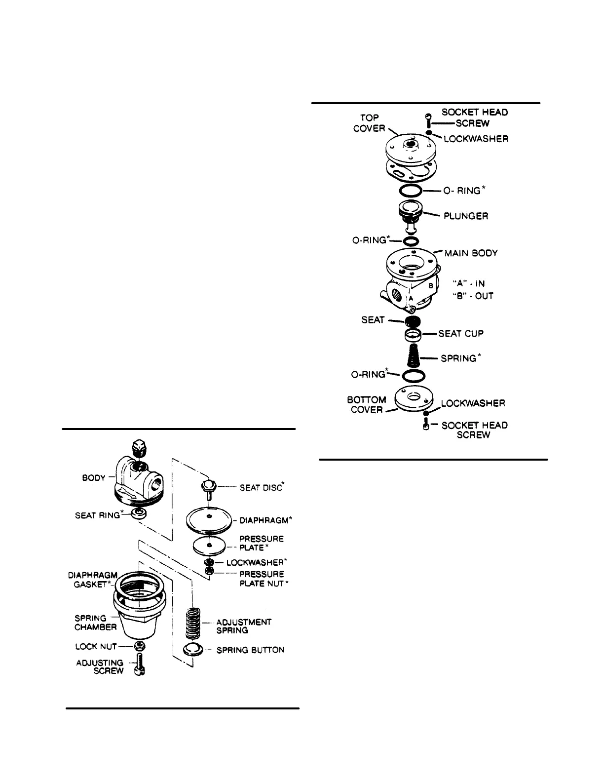
Refer to Figure 6-11. Pressure control regulator(P/N
406929) maintenance normally requires the replace-
ment of the internal diaphragm. Use repair kit No.
041742 and follow the procedure below for proper in-
stallation
1. Loosen the locknut and turn the adjusting screw
counterclockwise until the inner spring tension is
relieved. The adjusting screw should turn freely
when the spring tension is relieved.
2. Remove the spring chamber from the body to al-
low access to the internal parts.
3. Next, remove the spring button and the spring.
The dampener will stay inside the spring as it is re-
moved. Leave the dampener inside the spring as
there is no need to remove it.
4. After removing the spring, remove the gasket stop
and brass gasket.
5. At this time, remove the pressure plate nut and
disassemble the pressure plat, diaphragm, dia-
phragm gasket seat disc and seat gasket.
6. Remove and discard the seat ring.
7. The next step is to reassemble the regulator using
Figure 6-11 Pressure Regulator (P/N 406929)
* Repair Kit P/N 041742
Figure 6-12 Blowdown Valve (P/N 044912)
* Replacement Kit P/N 046782
the new parts provided in the repair kit.
8. Reassemble the diaphragm, pressure plate, gas-
ket, seat disc and seat disc gasket and tighten the
nut. All of the these parts with the exception of
pressure plate are provided in the repair kit.
9. Replace the seat ring with the new seat ring pro-
vided.
10. Replace the existing brass gasket and diaphragm
gasket stop.
11. Next, place these parts intheir proper place on the
body and replace the spring as it was prior to dis-
assembly.
12. Place the spring button over the spring as shown.
13. With all parts in order, replace the spring chamber
and tighten.
14. Tighten the adjusting screw until tension is real-
ized.
15. At this time, refer to Control System Adjustment
Procedure to readjust the control regulator.
BLOWDOWN VALVE MAINTENANCE
Refer to Figure 6-12. Blowdown valve (P/N 044912)
maintenance is limited to replacement of the internal
diaphragm. Use replacement diaphragm kit No.

 Loading...


