Section 6
MAINTENANCE
26
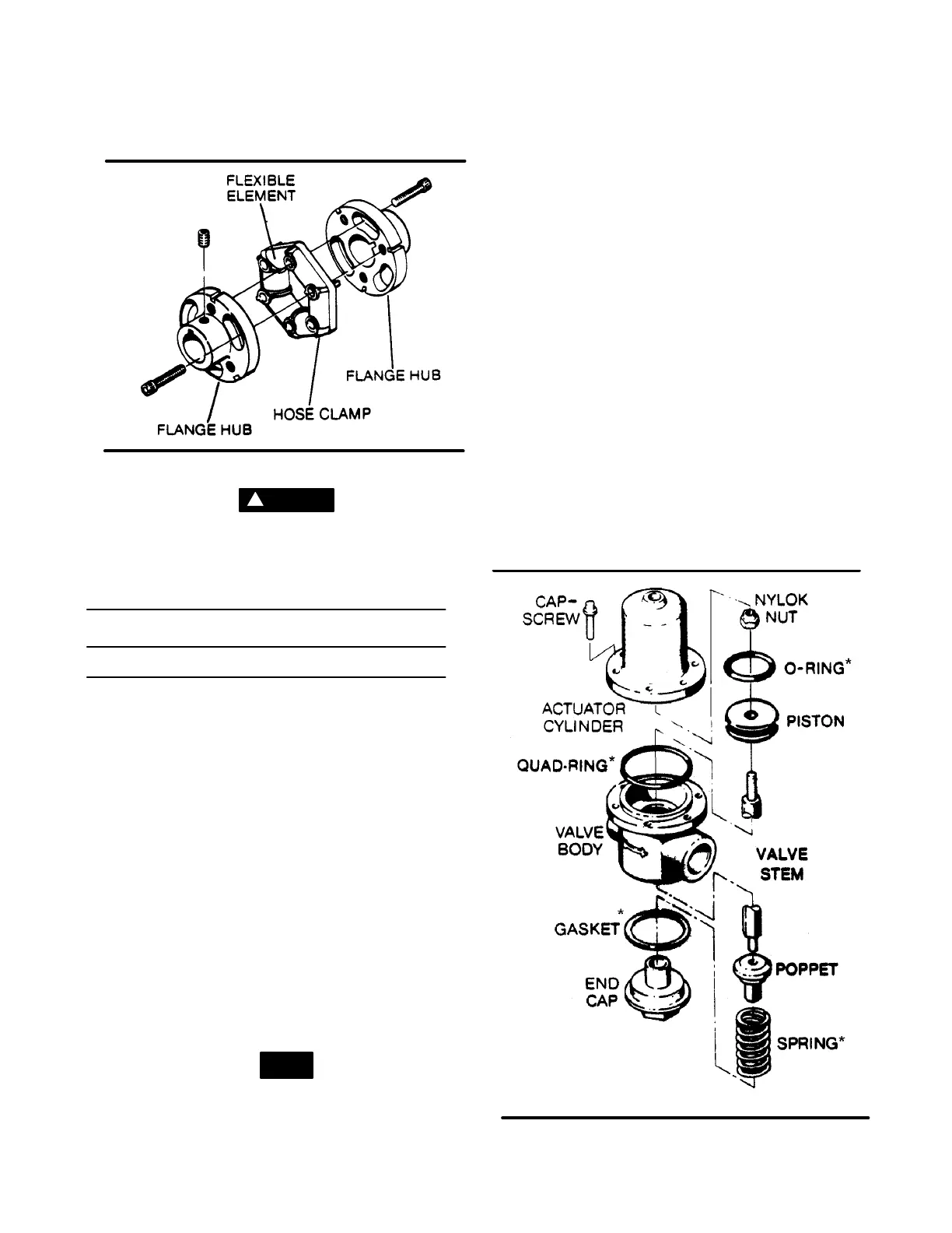
Figure 6-9 Drive Coupling
DANGER
!
Disconnect all power at source, before attempting
maintenance or adjustments.
TABLE 1
INSTALLATION DATA - SERIES 12&16 (40 THRU 75HP)
Horsepower
Coupling
Element
Coupling
Hub Gap
Tightening
Torque (Wet)
40 & 50 250004-641 1 13/16”
55 ft./lbs.
60 & 75 250018-551 2 1/16” 110 ft./lbs.
(75Nm)
(149Nm0
STEP 1 - MOUNT HUBS
Mount the motor hub and the compressor hub on its
respective shaft.
STEP 2 - COUPLING HUB GAP CHECK
Position the compressor hub, on the compressor
shaft, so that the hub is against the shaft shoulder
and tighten the hub setscrew. Position the motor hub
on the motor shaft and let it float.
STEP 3 - INSTALL THE FL EXIBLE ELEMENT
Insert the flexible element between the two hubs.
The element should be compressed prior to inser-
tion. The element can be compressed by tighteninga
suitable sized radiator hose clamp around the outer
edge of the element as shown in Figure 6-9. Slide the
ferry head bolts with lockwashers through the hoses
in the hubs and element. Torque these bolts as
shown in Table 1.
NOTE
DO NOT substitute the ferry head bolts, supplied
with the coupling.
After tightening the bolts, tighten the set screws and
remove the hose clamp f orm the flexible element.
Check the coupling gap as shown in Table 1. At this
time, the coupling is ready for operation.
DRIVE COUPLING DISASSEMBLY AND RE-
MOVAL
Refer to Figure 6-9. Disassembly and removal of the
drive coupling is done in the following manner:
1. Place a suitable sized radiator hose clamp overthe
flexible element as show in Figure 6-9 and tighten
sufficiently to compress the rubber.
2. Remove the ferry head bolts from the hubs and
element.
3. Rotate the element until the studs clear the hubs.
4. Remove the element from the hubs with the hose
clamp still in place.
5. Loosen the shaft setscrews and remove the hubs.
FLUID STOP VALVE
Refer to Figure 6-10. When servicing fluid stop valve
(P/N 016741), order repair kit No. 001684 and follow
the instructions below.
1. Remove the capscrews securing the cylinder to
the valve body and remove the cylinder. Inspect
Figure 6-10 Fluid Stop Valve (P/N 016741)
* Replacement Kit P/N 001684

 Loading...


