Section 6
MAINTENANCE
25
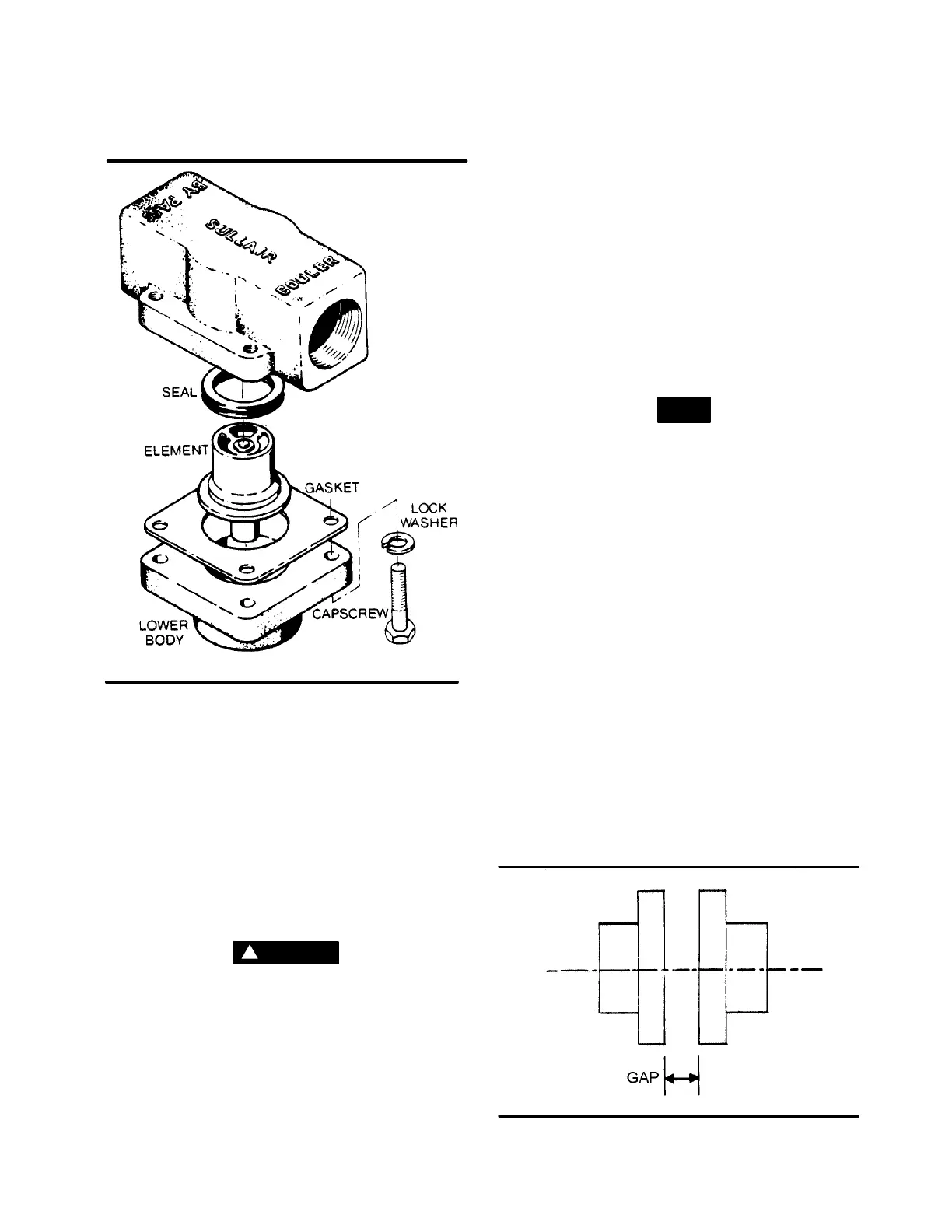
Figure 6-7 Thermal Valve (P/N 014512)
* Repair Kit P/N 001168
1. Unscrew the minimum pressure/check valve (P/N
241581) from the receiver cover.
2. Remove the hexagonal retaining cap from the
main body.
3. Remove the flat washer and heavyspring from the
main body.
4. Tap the piston assembly (with a screwdriver) from
the bottom of the main body and remove. The O-
ring will now be seen easily.
5. Remove the seal ring and discard.
6. Clean piston assembly and valve thoroughly.
7. Replacesealringand coat the piston and seal with
Parker Super “O” Ring Seal or an equivalent qual-
ity grease.
WARNING
!
Extreme caution s hould be used when removing
the cap from the body because there is spring ten-
sion on the cap.
8. Reset piston assembly into the main body and re-
position spring and flat washer.
9. Replace retaining cap.
10. Reattach valve to receiver cover and reconnect all
piping.
THERMAL VALVE MAINTENANCE
Refer to Figure 6-7. For thermal valve (P/N 014512)
maintenance, order repair kit No. 001168 which con-
sists of the following Sullair parts: 1 quad ring (P/N
046425) 1 gasket (P/N 049812), and if necessary, 1
thermal element (P/N 049542). Follow the procedure
explained below for installation.
DISASSEMBLY
1. Remove the appropriate piping from the thermal
valve before starting disassembly.
2. Remove the four (4) capscrews holding the hous-
ing together and separate the upper housing from
the lower housing.
3. Remove the gasket from between the housings.
4. Pull firmly on the thermal element and remove.
NOTE
There will be a slight resistance from the seal ring
centered in the lower housing.
5. Remove the seal ring from the lower housing and
discard.
REASSEMBLY
1. Grease and replace the O-ring in the center of the
lower housing.
2. Reinsert the thermal element pushing down until
the brass ring is flush with the surface of the lower
housing.
3. Position a new gasket on the lower housing mak-
ing sure holes are properly aligned.
4. Place the upper housing on the lower housing and
retighten the capscrews.
5. Replace all piping connected to the thermal valve.
DRIVE COUPLING INSTALLATION AND MAIN-
TENANCE
Refer toFigures 6-8and 6-9.For couplinginstallation
and maintenance the tools required will be ameasur-
ing scale, one set of standard Allen Wrenches, and
one set of standard socket wrenches.
For installation and maintenance of the drive cou-
pling, follow the steps explained below.
Figure 6-8 Drive Coupling “Hub” Gap Check

 Loading...


