Section 6
MAINTENANCE
24
Figure 6-5 Pressure Switch (P/N 040694)
desired pressure, the pressure switch setting will re-
quire adjustment (refer to Figure 6-5).
DANGER
!
DO NOT touch the electrical contacts, terminal or
leads with any metallic object. Severe electrical
shock may occur.
FOR PRESSURE RANGE ADJUSTMENT:
1. Remove cover to pressure switch.
2. Turn the range adjusting screw to the high pres-
sure setting. Turning the screw counterclockwise
lowers both the high and low pressure equally.
FOR DIFFERENTIAL ADJUSTMENT:
Differential is the difference between the high and
low pressure settings, 10 PSIG (7kPa) is typical.
Turn the differential adjusting screw to the lower (re-
set) setting. Turning the screw counterclockwise
widens the differential by lowering the reset (lower)
setting only.
When the pressure switch adjustment is complete,
the pressure regulator should be adjusted for the
pressure at which modulation of air delivery should
begin. In this case, that pressure will be 100 PSIG
(689kPa). The regulator is adjusted by loosening the
jam nut on the end of the cone shaped cover of the
pressure regulator (refer to Figure 6-11 for the loca-
tion). With the jam nut loose, turnthe adjusting screw
clockwise to increase or counterclockwise to de-
crease the setting.
Above 100 PSIG (689kPa), the regulator should al-
low pressure to flow into the control chamber of the
Sullicon Control. The Sullicon Control lever should
start to move at this time.
Cycle the control system several times and recheck
all pressure settings.
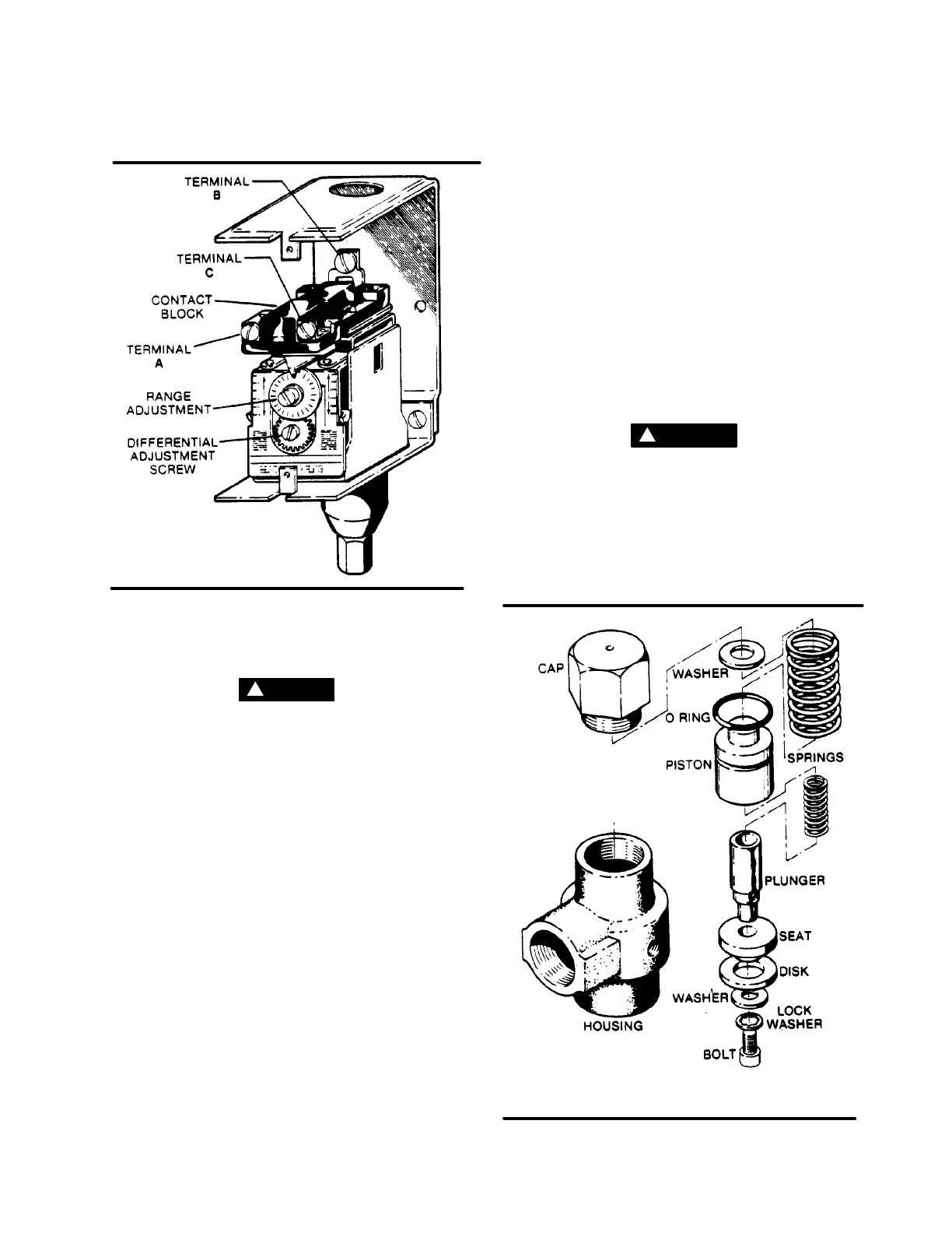
MINIMUM PRESSURE/CHECK VALVE MAINTE-
NANCE
Refer to Figure 6-6. Minimum pressure/check valve
(P/N241581)maintenanceis quiteminimal. Theonly
part which normally requires replacement is the O-
ring on the piston. To replace this ring, order seal re-
pair kit No. 250020-344. and follow the procedureex-
plained below.
WARNING
!
Before performing maintenance on the valve, be
sure that all pressure has been relievedin thecom-
pressor sump, and all downstream pressure has
been vented to the atmosphere. Also be sure that
the components of the compressor are cool to the
touch.
Figure 6-6 Minimum Pressure / Check Valve
(P/N 241581 - 12 Series)
* Repair Kit P/N 250026-758 - 12 Series
(P/N 250016-618 - 16 Series)
** Repair Kit P/N 250019-444 - 16 Series

 Loading...


