Section 6
MAINTENANCE
23
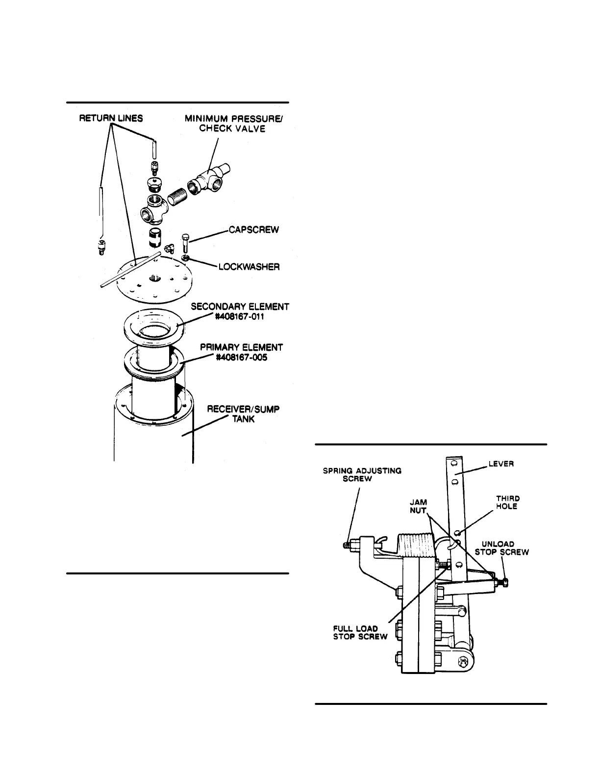
Figure 6-3 Separator Element Replacement
* Replacement element P/N 250034-116
** Replacement element P/N 250034-118
(primary - 16 Series)
(primary - 12 Series)
Replacement element P/N 408167-011
(secondary - 12 Series)
Replacement element P/N 408167-011
(secondary - 16 Series)
3. Loosen and remove the eight (8) hex head
capscrews (5/8“ x 2”) from the cover plate.
4. Lift the cover plate from the sump.
5. Remove the primary (250034-116) andsecondary
(250034-118).
6. Inspect the receiver/sump tank for rust, dirt, etc.
7. Scrape the old gasket material from the cover and
flange on the sump. Be careful not to let the
scraps fall in the sump.
8. Reinsert theseparatorelements (P/N 250034-116
and 250034-118) into the sump taking care not to
dent it against the tank opening.
9. Clean the underside of the receiver/sump tank
cover and remove any rust. Paint surface with an
epoxy paint.
10. Replace the cover plate, washers and capscrews.
Torque to 55 ft./lbs. (75 Nm).
11. Reconnect all piping making sure return line tubes
extend to the bottom or 1/4” above the bottom of
the separator element. This will assure proper
fluid return flow to the compressor.
12. Clean both return line strainers before restarting
the compressor.
CONTROL SYSTEM ADJUSTMENT
Refer to Figures 6-4 and 6-5. Prior to adjusting the
control system, it is necessary to determine the de-
sired operating pressure range and also the maxi-
mum pressure at which your compressor is to oper-
ate. The pressure must not exceed the maximum op-
erating pressure which is stamped on the compres-
sor serial number nameplate. The following explana-
tion applies to a typical installation with a desired op-
erating range of 100 to 110 PSIG(689 to 758kPa).
This information will apply to a compressor with any
other operating range except for the stated pres-
sures.
Remove the appropriate panels and covers to the
pressure switch, pilot valve, and pressure regulator.
With the shut-off valve closed (or slightly cracked
open) start the compressor. Observe the line pres-
sure gauge and pressure switch contacts. When the
linepressurereaches the desired pressure, thepres-
sure switch contacts should open. If the pressure
switch contacts do not open or they open prior to the
Figure 6-4 Sullicon Control
* Repair Kit P/N 250020-353

 Loading...


