Section 2
DESCRIPTION
12
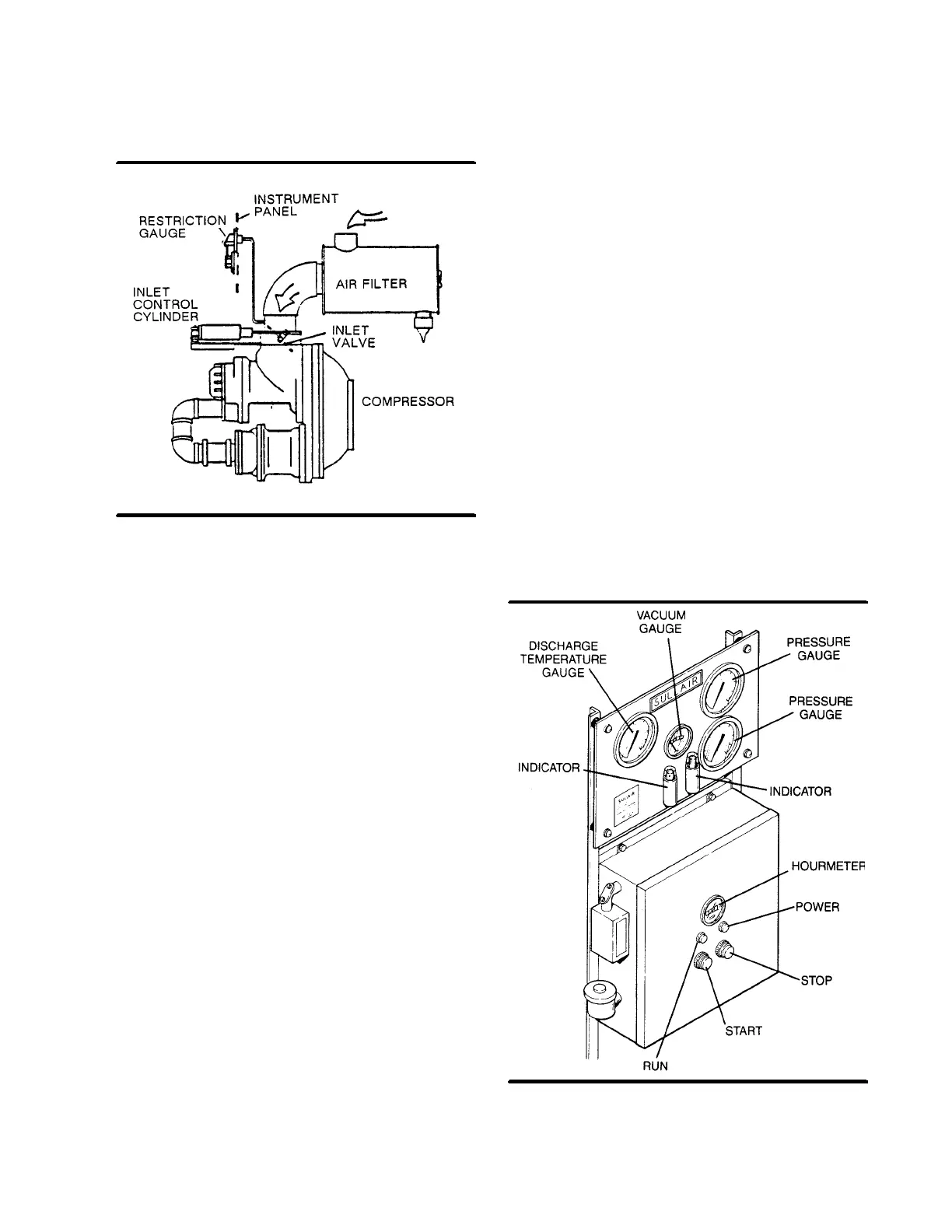
Figure 2-7 Air Inlet System (Typical)
2.7 AIR INLET SYSTEM, FUNCTIONAL DE-
SCRIPTION
Ref er t o F igure 2 -- 7. T he compressor inlet syst ems
consists of a dry--type air filter, a restriction gauge,
inlet cylinder, Sullicon Control and an air inlet valve.
The restriction gauge, located on the compressor in-
strument panel, indicates when air filter mainte-
nance is required.
The butterfly--type air inlet valve directly controls the
amount of air intake to the compressor in response
to the operation of the Sullicon Control (Section 2.6).
The inlet cylinder holds the butterfly valve closed
during the compressor start mode.
2.8 INSTRUMENT PANEL GROUP, FUNCTIONAL
DESCRIPTION
Ref er t o F igur e 2 -- 8 f or s pec if ic loc at ion of par t s de-
scribed. The instrument panel group consists of a
line pressure gauge
,
air filter maintenance
gauge
,
sump pressure gauge
,
compressor dis-
charge temperature gauge
and
maintenance in-
dicators
for the
separator element
and
bearing
filter
all located on a heavy gauge instrument panel.
Located on the electric control panel are
START
,
STOP
and
RESET
pushbuttons, power and run indi-
c at or s , an hour m et er, plus v ar ious ( opt ional) f ault in-
dic at or light s ( s ee F igur e 2 -- 7) .
Ref er t o F igur e 2 -- 3 f or f unc t ional loc at ions of t he f ol-
lowing indicators and controls:
S
The
line (terminal) pressure gauge
is connected
to the dry side of the receiver downstream from the
check valve and continually monitors the air pres-
sure.
S
The
sump pressure gauge
continually monitors
the sump pressure at the various load and/or unload
conditions.
S
The
discharge temperature gauge
monitors the
temperature of the air leaving the compressor unit.
The normal reading for the compressor is 230
_
F
(110
_
C).
S
The
START pushbutton
turns the compressor
on.
S
The
STOP pushbutton
turns the compressor off.
S
The
RESET pushbutton
clears the protective
shutdown interlocks after a fault has been cor-
rected.
S
The
hourmeter
records the cumulative hours of
operation for the compressor and is useful for plan-
ning and logging service operations.
S
The
separator maintenance indicator
monitors
the condition of the separator element and shows
red when the element restriction is excessive.
S
The
bearing lube filter maintenance gauge
monitors the condition of the bearing filter element
and shows red when the element should be
changed. This indicator is automatically reset.
Figure 2-8 Instrument Panel

 Loading...

