Section 7
ILLUSTRATIONS AND PARTS LIST
45
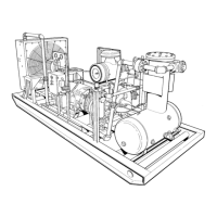
7.7 DISCHARGE SYSTEM
key part
number description number quantity
1 element, separator
(I)
409805--006 1
2 valve, relief 1” 245766 1
3 valve, minimum press 100PSIG (689kPa)
(II)
018498A 1
4 elbow, tube--m 1/4” x 1/4” 810504--025 5
5 tubing, steel 1/4” (ft.) 841115--004 20 feet
6 valve, check 21/2” 240182 1
7 threadolet, pipe 1/4” 808100--025 1
8 cap, fluid fill 048063 1
9 adapter, fluid fill 223061 1
10 tee, reducing 2” x 2” x 11/2” 806708--086 1
11 glass, sight fluid level 2” 048046 1
12 nipple, pipe 2” x close 822232--000 5
13 receiver, air/fluid separator 047571 1
14 nipple, pipe 1/2” x close 822208--000 1
15 elbow, pipe 90
_
1/2” 806530--020 1
16 nipple, pipe 1/2” x 12” 822208--120 1
17 valve, shut off 1/2” 045626 1
18 elbow, pipe 90
_
3” 806530--120 2
19 nipple, half 3” x 10” 822448--100 1
20 coupling, flexible 3” 046817 1
21 nipple, half 3” x 8” 822448--080 1
22 nipple, pipe 3” x 17” 822248--170 1
23 valve, disch check 21/2”(500--750 CFM) 014424 1
valve, disch check 3” (800--960 CFM)
(III)
016732B 1
24 adapter , valve discharge 250002--048 1
25 gasket, 21/2” flange 046061 3
26 bushing, reducing 21/2” x 2” 807610--080 1
27 plug, pipe 1/4” 807800--010 1
28 aftercooler , (200HP thru 300HP) 250008--938 1
S
aftercooler, (350HP thru 400HP) 406722 1
29 elbow, pipe 90
_
2” 806530--080 3
30 flange, threaded 2” 820330--032 2
(continued on Page 45)
(I)
For maintenance on separator element no. 409805--006, order repair kit no. 250028--166.
(II)
For maintenance on minimum pressure valve no. 018498A, order repair kit no. 018514A.
(III)
For maintenance on discharge check valve no. 016732B, order repair kit no. 606208--001.
PLEASE NOTE: W HEN ORDERING PARTS, INDICATE SERIAL NUMBER OF COMPRESSOR

 Loading...