EasyManua.ls Logo

Sullair 3009P - User Manual

Sullair 3009P
146 pages
To Next Page IconTo Next Page
Loading...
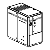
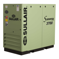
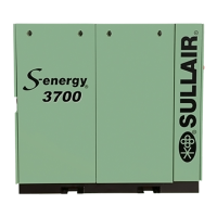
®SULLAIR®
INDUSTRIAL AIR COMPRESSOR
3000, 3000P, 3700, 4500,
3000V, 3000PV, 3700V, 4500V
30, 37 & 45 KW/40, 50 & 60HP
Air-Cooled and Water-Cooled
Standard & 24 KT
PART NUMBER:
02250155-601
KEEP FOR
FUTURE
REFERENCE
©
SULLAIR CORPORATION
The information in this document is
correct at the time of printing for utility
compressor serial number
20060701XXXX
and all subsequent serial numbers.
OPERATORS MANUAL AND PARTS LIST

Table of Contents

Questions and Answers:

Sullair 3009P Specifications

General IconGeneral
BrandSullair
Model3009P
CategoryAir Compressor
LanguageEnglish

Summary

Safety

Personal Protective Equipment (PPE)

Requirements for PPE during installation, operation, and maintenance.

Pressure Release Procedures

Procedures and requirements for safe pressure release in air lines.

Fire and Explosion Hazards

Safety precautions to prevent fire and explosion risks.

Moving Parts Safety

Guidelines for avoiding hazards associated with rotating and moving parts.

Hot Surfaces, Sharp Edges, and Corners

Precautions for avoiding injury from hot surfaces and sharp components.

Toxic and Irritating Substances

Handling and exposure guidelines for toxic or irritating substances.

Electrical Shock Prevention

Safety measures to prevent electrical shock hazards during maintenance.

Safe Lifting Procedures

Procedures for safely lifting and moving the compressor unit.

Description of Compressor

Description of Components

Identification and overview of the compressor package components.

Sullair Compressor Unit Functional Description

Detailed functional description of the Sullair rotary screw compressor unit.

Compressor Cooling and Lubrication System

Functional description of the cooling and lubrication system.

Compressor Discharge System

Functional description of the compressor discharge system.

Control System Functional Description

Functional description of the compressor control system.

Specifications and Diagrams

Wiring Diagram - MFV Air-Cooled

Wiring diagram for MFV air-cooled compressor models.

Wiring Diagram - MFV Water-Cooled

Wiring diagram for MFV water-cooled compressor models.

Wiring Diagram - Wye-Delta Air-Cooled

Wiring diagram for Wye-Delta air-cooled compressor models.

Wiring Diagram - Wye-Delta Water-Cooled

Wiring diagram for Wye-Delta water-cooled compressor models.

Wiring Diagram - VSD Air-Cooled

Wiring diagram for VSD air-cooled compressor models.

Wiring Diagram - VSD Water-Cooled

Wiring diagram for VSD water-cooled compressor models.

Wiring Diagram - VSD Air-Cooled, 575 V Series Delta

Wiring diagram for VSD air-cooled, 575V Series Delta models.

Wiring Diagram - VSD Water-Cooled, Series Delta 575 V

Wiring diagram for VSD water-cooled, Series Delta 575V models.

Installation Procedures

Ventilation and Cooling Requirements

Requirements for ventilation and cooling for air-cooled and water-cooled models.

Electrical Preparation and Wiring

Requirements for electrical installation, wiring, and grounding.

Maintenance Procedures

Troubleshooting Guide

Guide to diagnosing and resolving common compressor issues.

VSD Control Operation

VSD Control System Functional Description

Functional description of the VSD control system and operating phases.

Parts Lists and Diagrams

Control System and Electric Parts - MFV

Exploded view and parts list for MFV control system and electric parts.

Related product manuals