Section 2
DESCRIPTION
12
control valve, reducing air entering the compressor
until it matches the amount of air being used. The
control system functions continually in this manner
between the limits of 100 to 110 psig (6.9 to 7.6 bar)
in response to varying demands from the service
line.
The pressure regulator has an orifice which vents a
small amount of air to the atmosphere when the
pressure regulator controls the inlet control valve.
The orifice also bleeds any accumulated moisture
from the pressure regulator.
UNLOAD MODE - IN EXCESS OF 110 PSIG (7.6
BAR)
When a relatively small amount or no air is being
used, the service line pressure continues to rise.
When it exceeds 110 psig (7.6 bar), the Supervisor
Control System de--energizes the solenoid valve al-
lowing sump air pressure to be supplied directly to
close the inlet valve. Simultaneously, the solenoid
valve sends a pneumatic signal to the blowdown
valve. The blowdown valve opens to the atmo-
sphere, reducing the sump pressure to approxi-
mately 25 to 27 psig (1.7 to1.9 bar).The check valve
in the air service line prevents line pressure from re-
turningtothesump.
Whenthe linepressure drops to thelowsetting(cut--
in pressure; usually 100 psig [6.9 bar] on low pres-
sure [“L”] compressors and 115 psig [8.0 bar] on
high pressure [“H”] compressors, 140 psig [9.7 bar]
on [“HH”] compressors, 175 psig [12.0 bar] [“XH”] .
Supervisor energizes the solenoid valve and allows
the blowdown valve to close. The re--energized so-
lenoid valve again prevents line pressure from
reaching the inlet control valve.Should the pressure
begin to rise, the pressure regulator will resume its
normal function as previously described.
AUTOMATIC OPERATION
For applications with varied periods of time when
there are no air requirements, Supervisor’s AUTO-
MATIC mode allows the compressor to shutdown
(time delayed) when no compressed air require-
ment is present and restart as compressed air is
needed.
2.8 AIR INLET SYSTEM, FUNCTIONAL DE-
SCRIPTION
Refer t o F igur e 2 -- 5. T he C ompr es s or I nlet Sy s t em
consists of a
dry--type air filter
,a
restriction
gauge
and an
air inlet valve
.
The restriction gauge (located on the instrument
panel), indicates the condition of the air filter by
showing red when filter maintenance is required.
The poppet--type modulating air inlet valve directly
controls the amount of air intake to the compressor
in response to the operation of the pressure regula-
tor ( s ee Modulating Mode, Sec t ion 2.6 [Standar d
Elec tor / Mec hanic al] or Sec t ion 2.7 [O ptional Su-
pervisor Il]). The inlet valve also acts as a check
valve, thus preventing reverse rotation when the
Figure 2-5 Air Inlet System
compressor is shut down.
WARNING
!
“The Plastic Pipe Institute recommends against the
use of thermoplastic pipe to transport compressed
air or other compressed gases in exposed above
ground locations, e.g. in exposed plant piping.” (I)
Sullube should not be used with PVC piping sys-
tems. It may affect thebond at cemented joints. Cer-
tain other plastic materials may also be affected.
(I) Plastic Pipe Institute, Recommendation B,
Adopted January 19, 1972.
2.9 INSTRUMENT PANEL GROUP, FUNCTIONAL
DESCRIPTION - STANDARD ELECTRO-ME-
CHANICAL CONTROLLER
The electro-mechanical controller responds to sig-
nals from traditional pressure switch sensors and
provides
stop/start
,
common fault indication
,
sensor bypass timing
,
wye--delta transition tim-
ing
, and facilitates selectable
automatic restart
af-
ter power failure. Two--wire remote Stop/Start input
is provided.
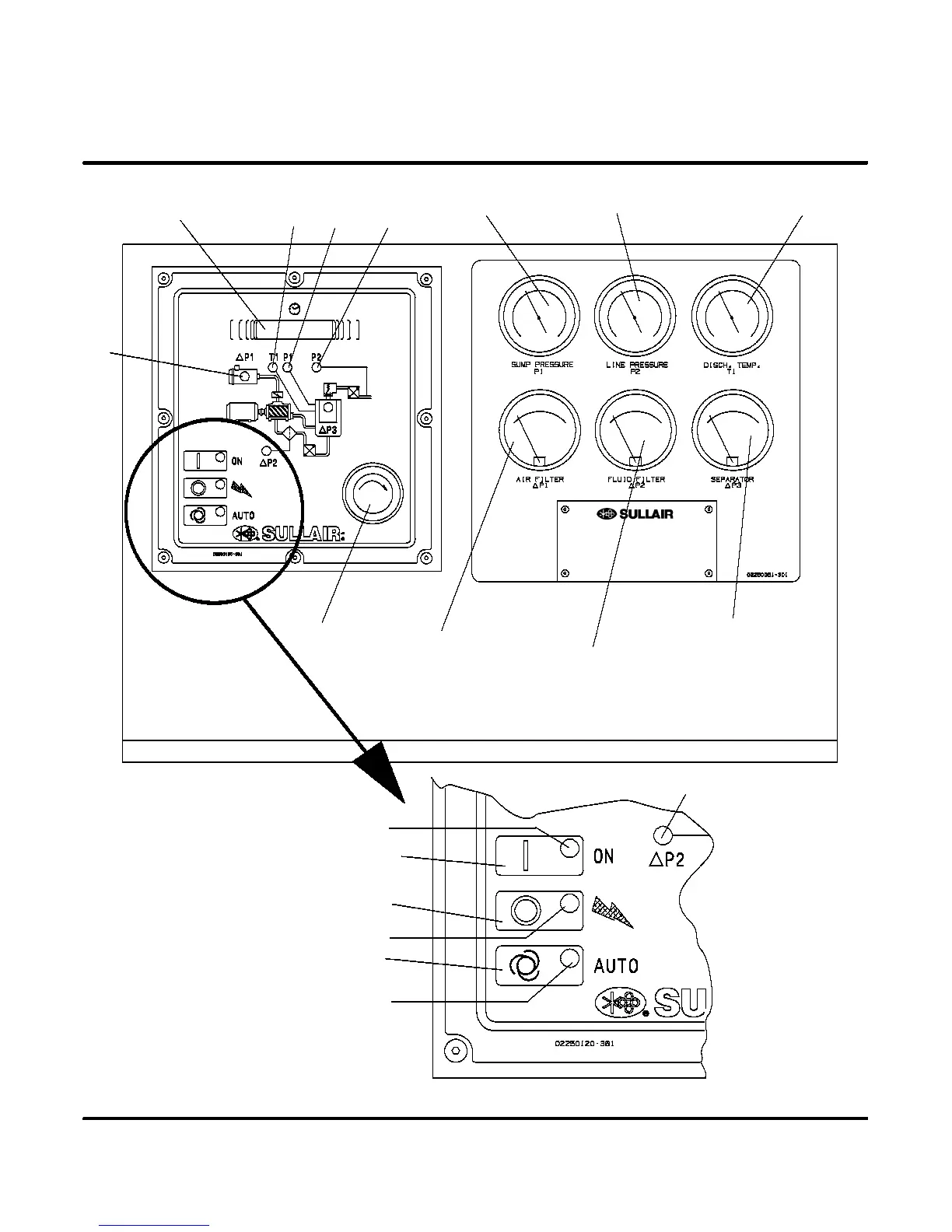
Refer t o F igur e 2 -- 6 f or s pec ific loc ation of par ts de-
scribed.
S
The
sump pressure gauge
continually monitors
the sump pressure at the various load and/or unload
conditions.
S
The
discharge temperature gauge
monitors the
temperature of the air leaving the compressor unit.
For both air--cooled and water--cooled compressors
the normal reading is approximately 180
_
F to 205
_
F
(82
_
Cto96
_
C).
S
The
separator maintenance gauge
monitors
condition of the separator element and shows in the
 Loading...